background image

Getting Started

2-5

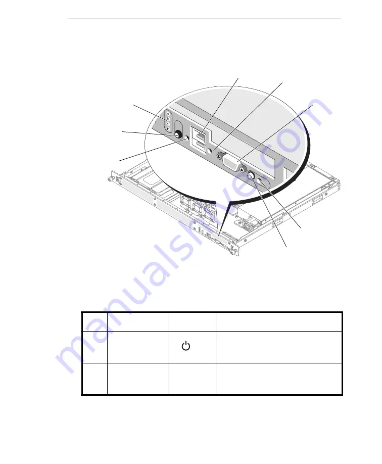
F

IGURE

2-2.   

Front panel

T

ABLE

 2-2.


Front panel features

I

TEM

C

OMPONENT

I

CON

D

ESCRIPTION

1

Power-on indi-
cator, power 
button

The power button turns the device on 
and off.


The indicator lights up when 

the device is on.

2

Diagnostic indi-
cators (4)

The diagnostic indicators aid in trou-
bleshooting hardware-related issues 
with technical support.

7

3

2

5

4

1

8

6

Summary of Contents for CR100 Series

Page 1: ...Network VirusWall TM Enforcer 1500i CR100 Series Network Security for Enterprise and Medium Business Installation and Deployment Guide Network Security ns...

Page 2: ...www trendmicro com download Trend Micro the Trend Micro t ball logo ActiveUpdate OfficeScan Control Manager and Network VirusWall are trademarks or registered trademarks of Trend Micro Incorporated Al...

Page 3: ...installing or using the product Detailed information about how to use specific features within the product are available in the Online Help and the Knowledge Base at the Trend Micro Web site Trend Mi...

Page 4: ...VirusWall Enforcer Network VirusWall Enforcer Overview 1 2 Key Concepts 1 3 Device Ports 1 3 Port Functions 1 4 Chapter 2 Getting Started Package Contents 2 2 Front Panel 2 4 Installing the Bezel 2 7...

Page 5: ...nts 3 8 Key Segments and Critical Assets 3 9 Dual Switch VLAN Environment 3 10 Single Switch VLAN Environment 3 12 Networks with IPv6 Addresses 3 13 IPv6 Limitations 3 13 Pure IPv6 Environments 3 14 D...

Page 6: ...onfiguration 4 4 Logging on the Preconfiguration Console 4 4 Configuring Device Settings 4 6 Enabling Ports and Selecting Port Functions 4 7 Setting the Interface Speed and Duplex Mode 4 9 Connecting...

Page 7: ...Trend Micro Network VirusWall Enforcer 1500i CR100 Series Installation and Deployment Guide vi...

Page 8: ...ks you need to perform to deploy the device It is intended for novice and advanced users of who want to plan deploy and preconfigure Network VirusWall Enforcer This preface discusses the following top...

Page 9: ...or downloadable from the Trend Micro Web site This IDG contains instructions for deploying the device a task that includes planning testing and preconfiguration See About This Installation and Deploy...

Page 10: ...ations and procedures on how to perform preconfiguration Troubleshooting and Technical Support troubleshooting tips for issues encountered during preconfiguration Ethernet Cable Usage Guidelines infor...

Page 11: ...onventions used in this document CONVENTION DESCRIPTION ALL CAPITALS Acronyms abbreviations and names of certain commands and keys on the keyboard Bold References to user interface items including men...

Page 12: ...ter introduces Trend Micro Network VirusWall Enforcer 1500i and provides an overview of important concepts and features This chapter discusses the following topics Network VirusWall Enforcer Overview...

Page 13: ...l Enforcer deployed at the network layer uses threat intelligence from Trend Micro to protect against threats as they enter the network The device scans all the traffic on a specific network segment a...

Page 14: ...erformance Regular port RJ 45 carries analyzed traffic to and from segments You can specify multiple regular ports Failopen a fault tolerance solution also known as LAN bypass that allows the Network...

Page 15: ...lar data ports and management ports Management ports can be assigned different functions as shown in the table below TABLE 1 1 Port types TYPE INTERFACE TYPE PORT NUMBER FUNCTION CODE DEFAULT STATE DE...

Page 16: ...usWall Enforcer to continue passing network traffic even if other device components fail or when the device loses power Note Management ports do not support failopen Management Copper ports 1 to 2 Man...

Page 17: ...Trend Micro Network VirusWall Enforcer 1500i CR100 Series Installation and Deployment Guide 1 6...

Page 18: ...g up and powering on a Trend Micro Network VirusWall Enforcer 1500i device This chapter discusses the following topics Package Contents on page 2 2 Front Panel on page 2 4 Back Panel on page 2 9 Techn...

Page 19: ...IGURE 2 1 Package contents Note The actual items in your package may appear slightly different from those shown in this document Refer to Table 2 1 to check whether the package is complete If any of t...

Page 20: ...B flash drive that can be used to restore the device operating sys tem and software This flash drive also includes tools and device documenta tion specifically Image file for the Network VirusWall Enf...

Page 21: ...e removable bezel Table 2 2 provides component descriptions 3 printed documents Security Appliance License Agreement Quick Start Guide Dell Product Information Guide Printed documents that provide saf...

Page 22: ...NT ICON DESCRIPTION 1 Power on indi cator power button The power button turns the device on and off The indicator lights up when the device is on 2 Diagnostic indi cators 4 The diagnostic indicators a...

Page 23: ...ce opera tion The amber device status indicator flashes when the device needs atten tion due to a hardware problem 7 Device identifi cation button You can use the device identification buttons on the...

Page 24: ...2 3 Network VirusWall Enforcer front panel Installing the Bezel The device is supplied with a removable bezel as shown in Figure 2 4 FIGURE 2 4 Network VirusWall Enforcer with the bezel To prevent use...

Page 25: ...he bezel slot on the right side of the device front plate 2 Rotate the other end of the bezel toward the front panel and press the bezel onto the panel to engage the latch 3 Lock the bezel To remove t...

Page 26: ...n the back panel FIGURE 2 6 Back panel 1 Power supply connector 2 Keyboard connector 3 Mouse connector 4 USB connectors 2 5 Serial connector 6 Video connector 7 Network port 1 8 Network port 2 9 NIC e...

Page 27: ...our port configuration Network Port Indicators Each Network VirusWall Enforcer port has an indicator that allows you to determine the port s current state Indicators on Onboard Ports Each onboard port...

Page 28: ...nnected at 1000Mbit s Technical Specifications The following table lists the technical specifications of Network VirusWall Enforcer TABLE 2 3 Indicator codes for onboard ports INDICATOR CODE STATUS Li...

Page 29: ...ice For freestanding installation ensure that the device has at least 2in 5 08 cm of clearance on each side to allow for adequate airflow and cooling WARNING Ensure that the fan vent is not blocked In...

Page 30: ...he kit contains two rail assemblies as well as screws and brackets for attaching the device Step 2 Install the rails and device in a rack Assemble the rails and install the device in the rack To assem...

Page 31: ...2 14 FIGURE 2 10 Sliding the inner member out to detach it 2 Using the provided screws attach the outer member to the rack frame FIGURE 2 11 Attaching the outer member to the rack frame 3 Using anoth...

Page 32: ...FIGURE 2 13 Mounting the device Step 3 Connect the keyboard and monitor optional Connect the keyboard and monitor The connectors on the back of your device have icons indicating which cable to plug i...

Page 33: ...power cable s to the device and if using a monitor connect the monitor s power cable to the monitor Step 5 Turn on the device Press the power button on the device and on the monitor optional The power...

Page 34: ...plan for the deployment It also provides deployment scenarios to help you understand the various ways the device can protect your network This chapter discusses the following topics Planning for Deplo...

Page 35: ...This Installation and Deployment Guide discusses phases 1 and 2 Refer to the Administrator s Guide for information related to phase 3 Phase 1 Plan the Deployment During phase 1 plan how to best deplo...

Page 36: ...on page 4 4 Connect the device s to your network see Connecting to the Network on page 4 10 Phase 3 Manage Devices During phase 3 manage Network VirusWall Enforcer devices from the Web console For th...

Page 37: ...eed and duplex mode Likewise allow your switch to auto select the port speed and duplex mode For IPv4 addresses the device supports addresses belonging to any class class A B or C For IPv6 addresses i...

Page 38: ...twork resources in the same manner as the endpoints already on your network and comprise essentially another internal network segment You must consider whether to protect remote endpoints as you do in...

Page 39: ...internal network as illustrated in the basic deployment scenario see Basic Deployment Scenario on page 3 17 The home user accesses both network resources and the Internet in the same way that interna...

Page 40: ...ure 3 1 FIGURE 3 3 Site to site VPN deployment scenario Figure 3 3 illustrates a VPN connection between two business units As in the home user scenario a VPN server is connected to a regular port on e...

Page 41: ...rastructure These endpoints are more likely to violate antivirus policies and introduce security risks to the network FIGURE 3 4 Guest network deployment scenario Figure 3 4 illustrates a segment of a...

Page 42: ...nts scenario The diagram above illustrates a segment of an internal network containing email and Web servers including endpoints An internal switch or hub is connected to a regular port see Key Concep...

Page 43: ...this means placing it between an upstream switch and one or more downstream switches Most VLAN configurations will utilize two switches Single switch VLAN configurations are possible for more informat...

Page 44: ...irusWall Enforcer 3 11 FIGURE 3 6 Multiple VLAN segments with each device protecting one segment In Figure 3 6 the devices are installed on an 802 1Q trunk line between two switches 802 1Q Trunk VLAN...

Page 45: ...s with each device protecting all segments Single Switch VLAN Environment A single switch configuration may have the following properties Possible only when using a switch that can be configured to ca...

Page 46: ...k VirusWall Enforcer in an environment with IPv6 addresses must plan carefully to ensure that the device can provide protection and does not interfere with network connectivity IPv6 Limitations Networ...

Page 47: ...vers are accessible only through IPv4 traffic When configured as an IPv6 only host Network VirusWall Enforcer traffic to and from the Internet can be translated using a dual stack proxy Dual Stack and...

Page 48: ...re it can scan the most traffic Determining the Number of Devices to Deploy Determine how many devices would best meet your security requirements Consider the following factors Existing network topolo...

Page 49: ...as OfficeScan and Control Manager Try to simulate the type of topology that would serve as an adequate representation of your production environment Creating a Contingency Plan Trend Micro recommends...

Page 50: ...device for deployment Basic Deployment Scenario The device can be installed on a network that contains Ethernet devices such as hubs switches and routers Deploy Network VirusWall Enforcer between a s...

Page 51: ...or system error that prevents it from filtering network packets Failopen Considerations Consider the following points when using failopen mode All regular ports ports 3 and 4 on the device support LAN...

Page 52: ...ses the following topics Before Preconfiguration on page 4 2 Understanding Preconfiguration on page 4 3 The Preconfiguration Console on page 4 3 Performing Preconfiguration on page 4 4 Connecting to t...

Page 53: ...dmin and PowerUser These accounts use admin and poweruser respectively as their default passwords Determine the host name for the device Verifying Network Support In a failopen deployment the total le...

Page 54: ...sole on page 4 3 3 Perform configuration tasks see Configuring Policy Enforcement and Device Settings in the Administrator s Guide After completing the initial configuration tasks see Preparing for Pr...

Page 55: ...gging on the Preconfiguration Console on page 4 4 2 Configuring Device Settings on page 4 6 3 Setting the Interface Speed and Duplex Mode on page 4 9 Logging on the Preconfiguration Console A few minu...

Page 56: ...Immediately after logging on to the Web console change the passwords to these accounts for increased security For more information see the Administrator s Guide 2 After logging on the Main Menu appear...

Page 57: ...evice settings 1 On the Main Menu of the Preconfiguration console type 2 to select Device Settings The Device Settings screen appears FIGURE 4 3 Device Settings screen Note When configuring the device...

Page 58: ...twork VirusWall Enforcer as a dual stack host provide both IPv4 and IPv6 settings WARNING If there is a NAT device in your environment Trend Micro recom mends assigning a static IP address to the devi...

Page 59: ...ole type 4 to open the Interface Settings screen FIGURE 4 4 Interface Settings screen 2 Type 2 to select Interface setting The Interface Settings screen changes so that the function of each port can b...

Page 60: ...Network VirusWall Enforcer port will operate in half duplex mode To simplify configuration you can set Network VirusWall Enforcer to auto select the optimum port speed and duplex mode However manual s...

Page 61: ...work 1 Connect one end of the cable to a regular port and the other to a segment of your network 2 Power on the device Note Network VirusWall Enforcer can handle various interface speed and duplex mod...

Page 62: ...g information for issues that may arise during the preconfiguration Tip Refer to the Administrator s Guide for answers to frequently asked questions and other troubleshooting tips This chapter discuss...

Page 63: ...is will remove any settings and policies stored on the device Note Reloading the Network VirusWall Enforcer image will restore the default settings You can only recover device settings if you exported...

Page 64: ...art of our technical support Web site the Trend Micro Knowledge Base contains the latest information about Trend Micro products To search the Knowledge Base visit http esupport trendmicro com Contacti...

Page 65: ...Guide 5 4 Having the following information ready before you contact our support staff can help them resolve problems faster Device model and image firmware version Deployment setup Interface speed and...

Page 66: ...OEM CR100 2 11 deployment identifying what to protect 3 4 number of devices 3 15 overview 3 2 planning 3 2 deployment scenarios 3 17 basic deployment 3 17 deployment strategy 3 16 device identificatio...

Page 67: ...es 3 4 IPv6 addresses 3 4 IPv6 networks 3 13 dual stack and mixed environments 3 14 limitations 3 13 pure environments 3 14 issues 5 2 K key network segments 3 9 keyboard 4 3 keylock 2 8 L LAN bypass...

Page 68: ...saving changes 4 10 timeout 4 5 preface vii printed documents 2 4 processor 2 11 Product Information Guide viii 2 4 PuTTY 4 3 Q Quick Start Guide 2 3 2 4 R rack cabinet 2 12 rack kit 2 3 2 13 RAS ser...

Page 69: ...Trend Micro Network VirusWall Enforcer 1500i CR100 Series Installation and Deployment Guide IX 4 V VGA 4 3 video connector 2 6 2 9 VLAN 3 12 VPN 3 5...

Reviews: