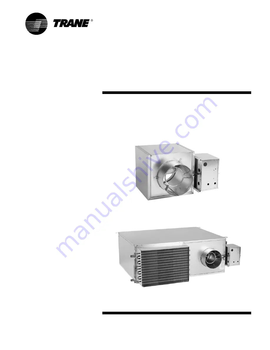
Installation/OperatorMaintenance
VariTrane™ Single-Ductand Fan-Powered Units
VAV-SVN01
E
-EN
June 2006
All VariTrane VAV Models with pneumatic, electronic, DDC controls and diffusers.
Page 1: ...Installation Operator Maintenance VariT rane Single Duct and Fan Powered Units VAV SVN01E EN June 2006 AllVariTraneVAV Models with pneumatic electronic DDC controls and diffusers...
Page 2: ...2006 American Standard All rights reserved VAV SVN01E EN...
Page 3: ...nging Bracket Locations Unit Weights Water Coil Connections Unit Accessibility Clearances Actuator Mounting Unit Setup 32 46 Flow Sensor P vs Airflow Delivery Maximum Fan MotorAmperage SCR Motor Speed...
Page 4: ...DDC Controller Cooling only DD12 LonTalk DDC Controller w N C on off hot water control DD13 LonTalk DDC Controller w proportional hot water control DD14 LonTalk DDC Controller on off electric heat co...
Page 5: ...ee unit drawings for outlet sizes damper information Digit 20 Not Used 0 N A Digit 21 Water Coil 0 None 1 1 Row 2 2 Row Digit 22 Electrical Connections VCCF VCWF can be flipped in the field to achieve...
Page 6: ...O cooling w PVRs DA stat PN08 PN N O heating N O cool act only RA stat PN09 PN N O htg clg vlvs w PVRs DA stat PN10 PN N O htg clg w PVRs cv disch DA stat Notes N C Normally closed N O Normally opene...
Page 7: ...J0 Design Sequence Factory assigned Digit 12 13 14 15 Controls ENON No controls field installed DDC or analog ENCL ENON with controls enclosure PNON No controls field installed pneumatic DD00 Trane e...
Page 8: ...n Powered Parallel Units con t Digit 30 Electric Heat Stages 0 None 1 1 Stage 2 2 Stages Equal 3 3 Stages Equal Digit 31 Contactors 0 None 1 24 volt magnetic 2 24 volt mercury 3 PE with magnetic 4 PE...
Page 9: ...ntrol FM00 FM customer actuator control FM01 FMTrane actuator w customer supplied controller VMA2 FM Johnson controlsVMA 1420 PWR1 FM Seimens 540 100 w GDE131 1P actuator PWR4 FM Seimens 540 100 w Tra...
Page 10: ...lectric Heat Kilowatts 000 None 050 0 5 kW 010 1 0 kW 015 1 5 kW 240 24 0 kW Digit 30 Electric Heat Stages 0 None 1 1 Stage 2 2 Stages Equal 3 3 Stages Equal Digit 31 Contactors 0 None 1 24 volt magne...
Page 11: ...lied controller VMA2 FM Johnson ControlsVMA 1420 PWR1 FM Seimens 540 100 w GDE131 1P actuator PWR4 FM Seimens 540 100 w Trane actuator PWR5 FM Seimens 540 100 w GDE131 1U actuator AT01 FMAutomated Log...
Page 12: ...65 6 5 kW 070 7 0 kW 075 7 5 kW 080 8 0 kW 090 9 0 kW 100 10 0 kW 1 10 11 0 kW 120 12 0 kW 130 13 0 kW 140 14 0 kW Fan Powered Low Height Parallel Units con t Service Model Number Description Digit 30...
Page 13: ...n controlsVMA 1420 PWR1 FM Seimens 540 100 w GDE131 1P actuator PWR4 FM Seimens 540 100Trane actuator PWR5 FM Seimens 540 100 w GDE131 1U actuator AT01 FMAutomated Logic U341V AT02 FMAutomated Logic U...
Page 14: ...4 0 kW 045 4 5 kW 050 5 0 kW 055 5 5 kW 060 6 0 kW 065 6 5 kW 070 7 0 kW 075 7 5 kW 080 8 0 kW 090 9 0 kW 100 10 0 kW 1 10 11 0 kW 120 12 0 kW 130 13 0 kW 140 14 0 kW 150 15 0 kW 160 16 0 kW 170 17 0...
Page 15: ...coils are not damaged y Locate and verify that the correct zone sensors are with the order These will be marked with an orange Accessories Enclosed label Store in a secure location until needed Acces...
Page 16: ...to the common outlet which leads to the zone being con trolled See Figure 2 The units are provided with a slip and drive rectangular duct connection or can be ordered with integral outlet plenum Seque...
Page 17: ...to the unit outlet which is mixed with primary air and delivered to the occupied space Note Either the fan the air valve or both can deliver airflow into the occupied space In order to prevent primary...
Page 18: ...rovided on these units since the unit should be supported by means of a hanger strap The hanger strap should be secured directly to the unit casing as shown in Figure 4 For cooling only single duct un...
Page 19: ...Attenuator Field Installed Primary Airflow TOP VIEW Parallel Cooling Hot Water Flow Ring Tubing Air Valve Airflow Discharge Outlet A B C D E F A D E F B C FAN SIZE 02SQ 03SQ 04SQ 05SQ 06SQ 07SQ 26 75...
Page 20: ...Plenum Inlet Optional Attenuator Field Installed Flow Ring Tubing Air Valve A B Electric Heater D G 19 00 483 mm F C B B C A D E FAN SIZE Elec Heat Only 3 25 83 mm 3 25 83 mm 3 25 83 mm 3 25 83 mm 41...
Page 21: ...enuator Field Installed 24 30 617 mm Primary Airflow Airflow Discharge Outlet 13 80 350 mm 4 00 102 mm 23 10 587 mm 3 35 85 mm TOP VIEW TOP VIEW 3 35 85 mm Airflow Discharge Outlet 31 65 804 mm 23 90...
Page 22: ...n Figure 9 Low Height Parallel10SQ Primary Airflow Air Valve 38 95 989 mm 1 625 41 mm Flow Ring Tubing 5 625 143 mm 41 137 1045 mm Airflow Discharge Outlet Optional Heater Terminal Box 5 625 143 mm TO...
Page 23: ...3 257 mm 3 35 85 mm 4 00 102 mm 27 00 686 mm 20 00 508 mm Primary Airflow Air Valve Airflow Plenum Inlet Optional Attenuator Field Installed Water Coil Primary Airflow Airflow TOP VIEW 19 86 504 mm 3...
Page 24: ...al Attenuator Field Installed Airflow Plenum Inlet 19 45 494 mm 19 45 494 mm 19 86 504 mm 3 35 85 mm 3 50 89 mm 3 50 89 mm 31 65 804 mm 19 86 504 mm Airflow Plenum Inlet Optional Attenuator Field Inst...
Page 25: ...ttom bracket not shown Bottom bracket to be installed in same orientation on bottom of unit Attenuator Installation Parallel Units 1 Attach attenuator to unit as shown with provided mounting brackets...
Page 26: ...ottom bracket not shown Bottom bracket to be installed in same orientation on bottom of unit Attenuator Installation Series Units 1 Attach attenuator to unit as shown with provided mounting brackets M...
Page 27: ...racket not shown Bottom bracket to be installed in same orientation on bottom of unit Attenuator Installation Low Height Parallel Units 1 Attach attenuator to unit as shown with provided mounting brac...
Page 28: ...ame orientation on bottom of unit Attenuator Installation Low Height Series Units 1 Attach attenuator to unit as shown with provided mounting brackets MOUNTING BRACKET OPTIONAL ATTENUATOR FIELD INSTAL...
Page 29: ...6 57 129 59 46 21 0803SQ 83 38 117 53 112 51 146 66 105 48 108 49 139 63 142 64 48 22 0804SQ 84 38 118 54 113 51 147 67 106 48 109 49 140 64 143 65 48 22 1002SQ 82 37 116 53 111 50 145 66 93 42 96 44...
Page 30: ...4 125 57 149 68 108 49 112 51 132 60 136 62 48 22 1406SQ 106 48 135 61 137 62 166 75 121 55 126 57 150 68 155 70 54 24 1407SQ 119 54 148 67 150 68 179 81 134 61 139 63 163 74 168 76 54 24 1606SQ 107 4...
Page 31: ...alve or pipe extensions to the water coil connections unless supported Unit Accessibility Single duct and dual duct units provided with hot water reheat have an access panel located on the side of the...
Page 32: ...Parallel Series 06SQ 1 2 3 8 3 3 4 6 Parallel Series 07SQ 1 4 7 3 8 6 6 Low height Parallel Series 08SQ 1 3 5 5 2 5 1 8 Low height Parallel Series 09SQ 1 3 5 5 2 5 1 8 Series Low height 10SQ 2 x 1 8...
Page 33: ...y efficient ECM motor as a motor option Balancing of an ECM motor is accomplished through electronic control adjustments on the ECM control board see Figure 15 Potentiometer settings for a multitude o...
Page 34: ...44 4 4 571 270 45 4 5 581 274 46 4 6 590 278 47 4 7 599 283 48 4 8 609 287 49 4 9 618 292 50 5 0 TENS UNITS CFM L sec Setting Switch Switch 627 296 51 5 1 637 300 52 5 2 646 305 53 5 3 655 309 54 5 4...
Page 35: ...374 45 4 5 806 381 46 4 6 819 387 47 4 7 832 393 48 4 8 845 399 49 4 9 859 405 50 5 0 TENS UNITS CFM L sec Setting Switch Switch 872 411 51 5 1 885 417 52 5 2 898 424 53 5 3 911 430 54 5 4 924 436 55...
Page 36: ...13 92 9 2 1739 821 93 9 3 1755 828 94 9 4 1771 836 95 9 5 1787 843 96 9 6 1802 851 97 9 7 1818 858 98 9 8 1834 866 99 9 9 1850 873 100 0 0 TENS UNITS CFM L sec Setting Switch Switch 280 132 1 0 1 296...
Page 37: ...2 1989 939 93 9 3 2005 946 94 9 4 2021 954 95 9 5 2037 961 96 9 6 2052 969 97 9 7 2068 976 98 9 8 2084 984 99 9 9 2100 991 100 0 0 TENS UNITS CFM L sec Setting Switch Switch 530 250 1 0 1 546 258 2 0...
Page 38: ...9 44 4 4 600 283 45 4 5 609 287 46 4 6 618 292 47 4 7 627 296 48 4 8 636 300 49 4 9 646 305 50 5 0 TENS UNITS CFN L sec Setting Switch Switch 655 309 51 5 1 664 313 52 5 2 673 318 53 5 3 682 322 54 5...
Page 39: ...92 9 2 1413 667 93 9 3 1426 673 94 9 4 1438 679 95 9 5 1451 685 96 9 6 1463 690 97 9 7 1475 696 98 9 8 1488 702 99 9 9 1500 708 100 0 0 TENS UNITS CFM L sec Setting Switch Switch 275 130 1 0 1 288 13...
Page 40: ...45 4 5 1123 530 46 4 6 1140 538 47 4 7 1157 546 48 4 8 1174 554 49 4 9 1192 562 50 5 0 TENS UNITS CFM L sec Setting Switch Switch 1209 570 51 5 1 1226 579 52 5 2 1243 587 53 5 3 1260 595 54 5 4 1277 6...
Page 41: ...5 4 5 1518 717 46 4 6 1536 725 47 4 7 1555 734 48 4 8 1573 742 49 4 9 1591 751 50 5 0 TENS UNITS CFM L sec Setting Switch Switch 1609 759 51 5 1 1627 768 52 5 2 1646 777 53 5 3 1664 785 54 5 4 1682 79...
Page 42: ...260 123 45 4 5 263 124 46 4 6 267 126 47 4 7 271 128 48 4 8 274 129 49 4 9 278 131 50 5 0 TENS UNITS CFM L sec Setting Switch Switch 282 133 51 5 1 285 135 52 5 2 289 136 53 5 3 293 138 54 5 4 296 140...
Page 43: ...87 277 44 4 4 594 281 45 4 5 602 284 46 4 6 610 288 47 4 7 618 292 48 4 8 626 295 49 4 9 634 299 50 5 0 TENS UNITS CFM L sec Setting Switch Switch 641 303 51 5 1 649 306 52 5 2 657 310 53 5 3 665 314...
Page 44: ...60 123 45 4 5 263 124 46 4 6 267 126 47 4 7 271 128 48 4 8 274 129 49 4 9 278 131 50 5 0 TENS UNITS CFM L sec Settings Switch Switch 282 133 51 5 1 285 135 52 5 2 289 136 53 5 3 293 138 54 5 4 296 140...
Page 45: ...548 259 44 4 4 556 262 45 4 5 563 266 46 4 6 570 269 47 4 7 577 272 48 4 8 584 276 49 4 9 592 279 50 5 0 TENS UNITS CFM L sec Setting Switch Switch 599 283 51 5 1 606 286 52 5 2 613 289 53 5 3 620 293...
Page 46: ...4 5 1036 489 46 4 6 1051 496 47 4 7 1065 502 48 4 8 1079 509 49 4 9 1093 516 50 5 0 TENS UNITS CFM L sec Setting Switch Switch 1107 523 51 5 1 1121 529 52 5 2 1135 536 53 5 3 1150 543 54 5 4 1164 549...
Page 47: ...UR Manual Reset Cutout Air Flow Switch Auto Reset Thermal Cutout Switch Optional Disconnect Door Controller 24V Output to Controller 24V Input from L1 L2 L3 G L1 L2 L3 L2 L1 L3 G Optional Transformer...
Page 48: ...7 347 480 LINE CONTACTORS HEATER P E with Magnetic Contactors PEMA P E with Mercury Contactors PEME N L2 L1 L3 G Line Voltage See Nameplate G N HEATER TERMINAL TYPICAL OF THREE PHASE VOLTAGES SINGLE D...
Page 49: ...t from Controller Output to Motor 115 or 277V OR BRN WH BK PUR Manual Reset Cutout Optional Air Flow Switch Auto Reset Thermal Cutout Switch Optional Disconnect Door Output to Motor 115 or 277V Contro...
Page 50: ...tactors PEMA P E with Mercury Contactors PEME N L2 L1 L3 G Line Voltage See Nameplate G N HEATER TERMINAL TYPICAL OF THREE PHASE VOLTAGES FAN POWERED UNITS PNEUMATIC CONTROL Door Optional Switch Disco...
Page 51: ...ER TERMINAL LINE VOLTAGE Fan powered Control Box with Pneumatic Controls Duct Pressure Switch Option BR BR TERMINAL W COM BK W BK BLOCK R 24V 1 3 TRANSFORMER MOTOR BK BR RELAY 24V BK 2 4 GREEN GROUND...
Page 52: ...CH DUCT C NC TRANSFORMER BK 24V Y BL CHOKE BL NO BL DISCONNECT BK SWITCH 3 FUSE FACTOR POWER W BK W SCREW 2 GROUND GREEN GR TERMINAL BK BLOCK MOTOR FAN Fan powered Control Box w ECM with Pneumatic Con...
Page 53: ...10 ONLY FAN OR FROM HEATER TERMINAL LINE VOLTAGE 5 CAPACITOR MOTOR CONTROL MOTOR RELAY SPEED NO PRESSURE SWITCH DUCT BL C NC TRANSFORMER BL Y FUSE BK BK L1 DISCONNECT BK BK SWITCH SCREW GROUND 2 N GR...
Page 54: ...OTOR 2 FAN TO VAV OR FROM HEATER TERMINAL LINE VOLTAGE MOTOR BL DUCT SWITCH PRESSURE TRANSFORMER BL BK 24V Y BL C NC NO FUSE 3 BK BK DISCONNECT SWITCH 2 W W SCREW GROUND GREEN GR W BK 4 Y BK TERMINAL...
Page 55: ...ing and fan wheel to be re aligned on a workbench or floor and prevent any possible fan wheel rubbing that may occur Removing the housing will provide access to the motor shaft set screw that holds th...
Page 56: ...e Ceiling Follow these procedures to finish installation of control and satellite diffusers and concealed spline for suspension ceilings before completing the ceiling construction Figure 30 Place the...
Page 57: ...VAV SVN01E EN 57 Maintenance Service Log Date T ag Serial Service Notes...
Page 58: ...58 VAV SVN01E EN Date T ag Serial Service Notes Maintenance Service Log...
Page 59: ...VAV SVN01E EN 59 Notes...
Page 60: ...E EN File Number SL TD 000 VAV SVN01E EN 0606 Supersedes SL TD 000 VAV SVN01D EN 0905 Stocking Location Inland Trane has a policy of continuous product and product data improvement and reserves the ri...