


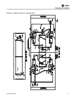


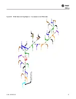

Figure 30.
Binding view for all LLIDs
Installation
RCDA-SVN002C-EN
23
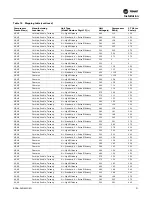
8. Validate configuration and setpoint values from the
Chiller Report PDF file that was created from
KestrelView. Within the Chiller Report PDF file, use the
search function to view the different sections.
9. In the case you changed any configuration or setpoint
values, click the Save button. This updates the values
on the UC800 controller and takes you to the LLID
Binding screen.
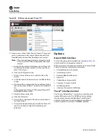
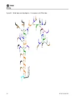
Figure 31.
Navigating within the equipment utility configuration tab in Tracer TU
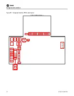
Figure 32.
Location of the equipment utility tab in Tracer TU
10. In Tracer TU, save a copy of the Chiller Service Report.
From the Reports drop-down menu, select and open
Chiller Service Report. See
Summary of Contents for Tracer AdaptiView
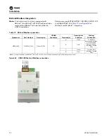
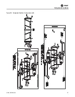
Page 29: ...Figure 36 Component location 2 compressor units Component Locations RCDA SVN002C EN 29 ...
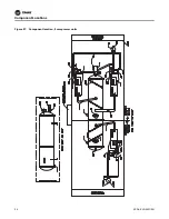
Page 30: ...Figure 37 Component location 3 compressor units Component Locations 30 RCDA SVN002C EN ...
Page 31: ...Figure 38 Component location 4 compressor units Component Locations RCDA SVN002C EN 31 ...
Page 33: ...Component Locations RCDA SVN002C EN 33 Page Left Intentionally Blank ...
Page 50: ......
Page 51: ...Figure 56 Back plate template in actual size 8 00 9 00 6 00 5 00 4X 266 RCDA SVN002C EN 51 ...
Page 52: ...Page left intentionally blank ...
Page 53: ......
Page 54: ......
Page 55: ......