background image

Required Opening = CFM / 300 FPM

Example:

Given:

Qty of 4 units in a mechanical yard, surrounded by a fence. Units are 2TWR3048A1 -

Required:

Determine free air opening space required in fence -

Solution:

4400 CFM X Qty of 4 = 17,600 CFM
17600 CFM / 300 FPM = 58.67 square feet
Round 58.67 to 59 square feet of free air opening in the 4 fence sections surrounding the mechanical yard.

*Table produced August 2006. For the most current information, please refer to specific equipment Product
Data.

Pg. 19

 XR13 and XR14 Outdoor Unit Airflow Table

2TTR3 / 2TWR3

2TTR4 / 2TWR4

4TTR3 / 4TWR3

4TTR4 / 4TWR4

Unit Model Number

CFM

Unit Model Number

CFM

Unit Model Number

CFM

Unit Model Number

CFM

2TTR3018A1

1565

2TTR4018A1

2000

4TTR3018A1

3010

4TTR4018A1

2250

2TTR3024A1

2500

2TTR4024A1

2800

4TTR3024A1

3160

4TTR4024A1

2725

2TTR3030A1

3320

2TTR4030A1

3100

4TTR3030A1

3160

4TTR4030A1

2900

2TTR3036A1

4400

2TTR4036A1

3100

4TTR3036A1

3160

4TTR4036A1

3100

2TTR3042A1

4400

2TTR4042A1

4400

4TTR3042A1

4610

4TTR4042A1

4150

2TTR3048A1

4800

2TTR4048A1

4400

4TTR3048A1

4610

4TTR4048A1

4150

2TTR3060A1

4800

2TTR4060A1

4400

4TTR3060A1

4610

4TTR4060B1

4150

2TWR3018A1

1565

2TWR4018A1

2230

4TWR3018A1

3170

2TWR3024A1

2485

2TWR4024A1

2835

4TWR3024A1

3170

4TWR4024A1

2710

2TWR3030A1

2800

2TWR4030A1

3915

4TWR3030A1

3170

4TWR4030A1

3200

2TWR3036A1

4400

2TWR4036A1

4100

4TWR3036A1

4820

4TWR4036A1

4100

2TWR3042A1

4400

2TWR4042A1

4244

4TWR3042A1

4820

4TWR4042A1

4200

2TWR3048A1

4400

2TWR4048A1

4185

4TWR3048A1

4820

4TWR4048A1

4200

2TWR3060A1

4960

2TWR4060A1

4250

4TWR3060A1

4820

4TWR4060A1

4090

Summary of Contents for SSC-APG002-EN

Page 1: ...Application Guide SSC APG002 EN For Trane XR Style Split Condensing Units and Heat Pumps Low OD Ambient Operation Unit Mounting Minimum Clearances ...

Page 2: ...ling Operation III UnitMounting IV Minimum Operating Clearances ISSUEDBY Product Application Engineering Department Trane Tyler Texas Pg 2 POSITION STATEMENT The Trane Company has always recommended installing Trane approved matched indoor and outdoor systems All Trane split systems with a nominal rating of 13 SEER and above are listed in the ARI Certified Directory with thermostatic expansion val...

Page 3: ...utdoor ambients The BAYLOAM103 will cycle the condenser fan motor in order to achieve adequate operating head pressure The control is adjustable Evaporator Defrost Control A device that is field installed on the system s indoor coil in order to prevent the system from running during the cooling cycle when the indoor coil approaches or reaches a temperature in which frost will form on the coil surf...

Page 4: ...motor For more information publication number 18 HE46D1 1or latest version should be consulted Unit requires a compressor crankcase heater and start accessory only if it is not factory installed Check general specifications located in product data to determine if unit is equipped with factory installed quick start components Solenoidvalverequiredif 1 Liquidlineisonesizelargerthanfactoryconnection ...

Page 5: ... R Y YLow Orange Green G White W1 White W2 White W3 Blue B R Y O G W X2 B Red Yellow Orange Brown X2 Blue EDR 1 EDC EDR Y B Red R Y YLow Green G White W1 White W2 White W3 Blue B EDC Heat Pump Split System andAY28X084 Evaporator Defrost Control Thermostat Air handling unit Thermostat Pg 5 Heat pump unit Air handling unit Cooling unit ...

Page 6: ...nitsandheatpumpspleaseobservethe following 1 Anytimetheunitistobesupportedfromtheedge thesupportingmaterialmustextendminimumtwo inches beyond the perimeter of the unit s base 2 Themountingholelocationsaremoldedinthebasepan however mustbedrilledthrough a Hole locations are identified on page 7 and 8 of this document as well as the unit installation guide 3 Washers should be placed in between the fa...

Page 7: ...ust extend under the base pan at least 2 Trane recommends supporting the middle of the base pan with a cross member support must extend 2 from the basepan perimeter support center of unit Pg 7 BASE PAN MOUNTINGHOLE LOCATIONS location only holes must be drilled ...

Page 8: ...the basepan perimeter support center of unit support must extend 2 from the basepan perimeter support center of unit If supporting the base pan from the perimeter the support must extend under the base pan at least 2 Trane recommends supporting the middle of the base pan with a cross member Pg 8 ...

Page 9: ...tween outdoor units and adjacent walls fences and other units Theobstructioninquestionisusuallyoneofthefollowing 1 One or more walls of an adjacent building 2 Fences or barriers provided to reduce sound transmission or visually screen the equipment 3 Otheroutdoorunitsinamulti unitinstallation 4 Acombination of the above 5 Overhangs Theprimeconsiderationsinvolvedinestablishingminimumclearancesare 1...

Page 10: ...aces 2 Installation of two or more units where two adjacent walls form a corner A For locations where the design ambient temperature is below 105F 1 Note the unit base size and obtain the minimum clearance values from the table below B For locations where the design ambient temperature exceeds 105F 1 2 0 feet clearance from both walls 2 3 0 feet clearance in between units unless service panels fac...

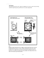
Page 11: ...3 123 SIngle Unit Solid Fence Multiple Units Solid Fence Solid Fence If fence height is taller than unit s provide openings in fence that will provide maximum 300 FPM air velocity These openings shall be located at the lower portion of the fence If acceptable the fence may be raised to provide open bottom clearance of fence height above the unit Service Clearance minimum clearance table If removab...

Page 12: ...ween the units In order to comply with NEC this may increase to 4 feet minimum clearance If wall or fence is to be constructed around the entire perimeter of the mechanical yard Maintain minimum 1 5 feet clearance from the units The fence height shall not exceed that of the unit It is recommended to install louvers in the fence to allow no greater than 300 feet per minute velocity Consult the tabl...

Page 13: ...ess Service Access Service Access Units may be rotated in order that service access sides face each other provided that 3 feet minimum clearance be maintained between the units In order to comply with NEC this may increase to 4 feet minimum clearance If wall or fence is to be constructed around the entire perimeter of the mechanical yard Maintain minimum 1 5 feet clearance from the units The fence...

Page 14: ... must meet NEC Article 110 16 requirements and local codes Note Minimum working clearance must be in compliance with the National Electric Code Currently the minimum clearance between a wood or suitable grounding material type fence requires minimum 3 feet If other material is used to form the windshield the minimum space may be increased to 3 5 feet Please consult the 2002 or current Edition of t...

Page 15: ...3FT 1 M 3 5FT 1 2 mm 4FT Note Where the conditions are as follows Condition 1 Exposed live parts on one side and no live or grounded parts on the other side of the working space or exposed live parts on both sides effectively guarded by suitable wood or other insulating materials Insulated wire or insulated busbars operating at not over 300 volts to ground shall not be considered live parts Condit...

Page 16: ...829 mm 32 5 8 756 mm 29 3 4 2TWR3030A1000AA 3 933 mm 36 3 4 829 mm 32 5 8 756 mm 29 3 4 2TTR3036A1000AA 3 832 mm 32 3 4 829 mm 32 5 8 756 mm 29 3 4 2TWR3036A1000AA 4 943 mm 37 1 8 946 mm 37 1 4 870 mm 34 1 4 2TTR3042A1000AA 4 841 mm 33 1 8 946 mm 37 1 4 870 mm 34 1 4 2TWR3042A1000AA 4 1045 mm 41 1 8 946 mm 37 1 4 870 mm 34 1 4 2TTR3048A1000AA 4 1045 mm 41 1 8 946 mm 37 1 4 870 mm 34 1 4 2TWR3048A1...

Page 17: ...829 mm 32 5 8 756 mm 29 3 4 2TWR4030A1000AA 4 841 mm 33 1 8 946 mm 37 1 4 870 mm 34 1 4 2TTR4036A1000AA 3 933 mm 32 3 4 829 mm 32 5 8 756 mm 29 3 4 2TWR4036A1000AA 4 943 mm 37 1 8 946 mm 37 1 4 870 mm 34 1 4 2TTR4042A1000AA 4 943 mm 33 1 8 946 mm 37 1 4 870 mm 34 1 4 2TWR4042A1000AA 4 1045 mm 41 1 8 946 mm 37 1 4 870 mm 34 1 4 2TTR4048A1000AA 4 1045 mm 41 1 8 946 mm 37 1 4 870 mm 34 1 4 2TWR4048A1...

Page 18: ...4 870 mm 34 1 4 4TTR3048A1 4 4TTR4048A3 4 1045 mm 41 1 8 946 mm 37 1 4 870 mm 34 1 4 4TTR3060A1 4 1045 mm 41 1 8 946 mm 37 1 4 870 mm 34 1 4 4TTR4060A3 4 4TWR3018A1 3 730 mm 28 3 4 829mm 32 5 8 756mm 29 3 4 4TWR4018A1 3 933 mm 36 3 4 829mm 32 5 8 756mm 29 3 4 4TWR3024A1 3 4TWR4024A1 3 1035 mm 40 3 4 829mm 32 5 8 756mm 29 3 4 4TWR3030A1 3 933 mm 36 3 4 829mm 32 5 8 756mm 29 3 4 4TWR4030A1 3 4TWR303...

Page 19: ...1565 2TTR4018A1 2000 4TTR3018A1 3010 4TTR4018A1 2250 2TTR3024A1 2500 2TTR4024A1 2800 4TTR3024A1 3160 4TTR4024A1 2725 2TTR3030A1 3320 2TTR4030A1 3100 4TTR3030A1 3160 4TTR4030A1 2900 2TTR3036A1 4400 2TTR4036A1 3100 4TTR3036A1 3160 4TTR4036A1 3100 2TTR3042A1 4400 2TTR4042A1 4400 4TTR3042A1 4610 4TTR4042A1 4150 2TTR3048A1 4800 2TTR4048A1 4400 4TTR3048A1 4610 4TTR4048A1 4150 2TTR3060A1 4800 2TTR4060A1 ...

Page 20: ...tp www trane com Literature Order Number FileNumber SSC APG002 EN 08 06 Supersedes XR APG05 EN 09 04 Stocking Location Since Trane has a policy of continuous product improvement it reserves the right to change design and specifications without notice ...

Reviews: