


70
RTAA-IOM-3
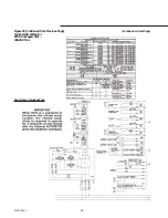
Alarm/Running/Maximum
Capacity Outputs
Terminals 1 to 8 on terminal strip TB4
of the 1U1 board provide a variety of
contact outputs. These are dependent
upon the setting of Menu Item 4E and
its relationship to diagnostics,
compressors operating and the system
operating at full capacity.
Table 11
Alarm/Running/Maximum
Capacity Relay Output
Configurations
Relay Output Configuration
1: RLY 1 = Alarm
RLY 2 = Compressor Running
RLY 3 = Maximum Capacity
2: RLY 1 = Circuit I Alarm
RLY 2 = Circuit 2 Alarm
RLY 3 = Maximum Capacity
3: RLY 1 = Alarm
RLY 2 = Circuit 1 Running
RLY 3 = Circuit 2 Running
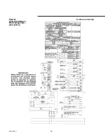
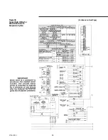
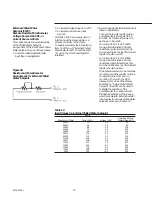
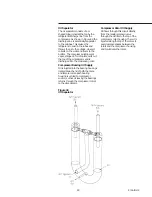
As shown in Figure 37, there are three
relays. Relays 1 and 2 have SPDT
contacts. Relay 3 has SPST normally
open contacts. The relays can provide
three different output configurations, as
shown in Table 11, and each
configuration offers four choices as to
how the alarm relay is to respond to a
set of diagnostics.
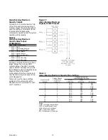
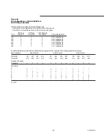
Table 12 shows the twelve settings
available in Menu Item 4E and the
diagnostics which are issued for each
set of conditions.
Figure 37
Alarm/Running/Maximum
Capacity Contact Outputs
Table 12
Alarm/Running/Maximum Capacity Menu Settings
Diagnostics that the
Relays Output
Alarm Relay(s) is Active
Menu Item 4E
Configuration
MMR/
MAR/
Setting
(Table 11)
CMR diag.
CAR diag.
IFW diag.
1
1
YES
NO
NO
2
1
YES
YES
NO
3
1
YES
YES
YES
4
1
YES
NO
YES
5
2
YES
NO
NO
6
2
YES
YES
NO
7
2
YES
YES
YES
8
2
YES
NO
YES
9
3
YES
NO
NO
10
3
YES
YES
NO
11
3
YES
YES
YES
12
3
YES
NO
YES
Notes:
MMR = Machine Manual Reset
CMR = Circuit Manual Reset
MAR = Machine Auto Reset
CAR = Circuit Auto Reset
IFW = Informational Warnings
Summary of Contents for RTAA-130
Page 2: ... American Standard Inc 1991 ...
Page 8: ...8 RTAA IOM 3 ...
Page 24: ...24 RTAA IOM 3 ...
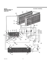
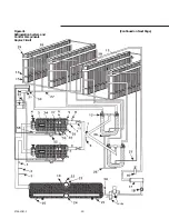
Page 50: ...50 RTAA IOM 3 Figure 30 Refrigerant Circuit Identification ...
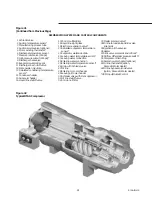
Page 52: ...52 RTAA IOM 3 Figure 31 Remote Evaporator Piping Example ...
Page 59: ...59 RTAA IOM 3 Continued from Previous Page See Notes on Next Page ...
Page 63: ...63 RTAA IOM 3 Continued from Previous Page See Notes on Page 61 ...
Page 65: ...65 RTAA IOM 3 Continued from Previous Page See Notes on Page 61 ...
Page 76: ...76 RTAA IOM 3 ...
Page 92: ...92 RTAA IOM 3 Figure 51 Operator Interface Controls ...
Page 120: ...120 RTAA IOM 3 ...
Page 127: ...127 RTAA IOM 3 Continued from Previous Page 2307 1566C ...
Page 128: ...128 RTAA IOM 3 Figure 57 Unit Sequence of Operation RTAA 130 to 200 Tons 2306 9122A ...
Page 132: ...132 RTAA IOM 3 Figure 58 Operator s Log ...
Page 138: ...138 RTAA IOM 3 ...


