


Since the Trane Company has a policy of continuous product improvement, it reserves the right to change specifications
and design without notice. The installation and servicing of the equipment referred to in this booklet should be done by
qualified, experienced technicians.
Installation
QFNA-IOM-1
Library
Service Literature
Product Section
Air Handling
Product
Fans
Model
Q Fan and Super Q II Fan
Literature Type
Installation/Operation/Mainteance
Sequence
QFNA-IOM-1
Date
August 1997
File No.
SV-AH-FAN-QFNA-IOM-1-897
Supersedes
FAN-IM-3-975
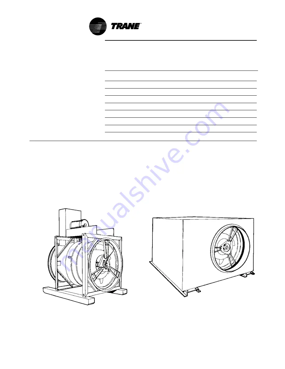
Model Q Fan and
Super Q II Plus ™
X39640481-01
©American Standard Inc. 1997


