background image


-


For maintenance and repair work, the power supply of the unit must be inter-
rupted. 

-


Use only suitable tools according to EN 1127-1:2011 to prevent sparking. 

-


Perform work only with conductive footwear (according to BGR 132) in order 
to avoid electrostatic charging. 

-


To avoid static charging, cleaning work may only be performed with a wet 
cloth. 

-


Work may only be performed at non-explosive atmosphere. 

-


The creation of an explosive atmosphere needs to be counteracted by ade-
quate ventilation. 

-


Avoid any kind of ignition sources. 


2.3  Staff selection and qualification 

 
All persons who are authorized to work on the air conditioner must, have read and understood this 
manual - in particular 

chapter 2 (Safety instructions)

. Before this is not guaranteed, the person 

may not begin to work on the AHU. 
 
All work must be carried out by professionals who have sufficient technical training, experience and 
sufficient knowledge of… 

-


Locally applicable safety and occupational health rules 

-


Locally valid accident prevention regulations 

-


Locally applicable standards and approved rules of practice. 

 
All professionals have to recognize and assess the work, recognize and avoid potential hazards.  
 

Execution of the assembly, installation, electrical connection, commissioning and disposal: 

-


by qualified electricians and AHU technicians. 

Execution of maintenance / monitoring of the operation: 

-


by technical staff or trained personnel and qualified electricians and AHU technicians. 

 
Work on optionally installed refrigeration components must be performed only by trained and ac-
cording to EU-directive 303/2008 certified refrigeration technicians. 
  
Subsequently, warning triangles indicate warnings that must be followed to minimize risks to per-
sons who are entrusted with the work on the air conditioner. 
 

Reception control / unloading / transportation to installation site 

 
Note: 

Chapter 3.2 (Unloading / transportation to installation location)

chapter 3.3 

(Overlifting of AHU sections with crane lugs)

 and 

chapter 3.4 (Overlifting of monoblocs)

 do 

not apply to flat units (ceiling units), since they are not equipped with base frame. 
 

3.1  Reception control 


-


Upon arrival of the equipment, please check immediately the package for completeness and 
damage. 

-


Loose supplied parts and assembly materials are in a nylon bag or a box in the unit. 

Summary of Contents for CCEB

Page 1: ...CCEB Air Handling Units July 2016 AH SVX01E GB Original instructions Installation Operation Maintenance...

Page 2: ...In addition to the instructions in this guide subject specific standards as well as local na tional and international regulations must be observed...

Page 3: ...the overlifting of both delivery sections on crane lugs as well as monoblocs 27 3 6 Storage 28 4 Foundation erection 28 4 1 Foundation 29 4 2 Erection 30 4 2 1 Potential risks that may arise through t...

Page 4: ...run 79 9 Maintenance 82 9 1 Control cabinet 82 9 2 Fan motor group 82 9 2 1 Fan 82 9 2 2 Motor 84 9 2 3 V belt drive 84 9 2 4 Re tensioning of belts 86 9 2 5 Replacing of belts 88 9 3 Air filters 88...

Page 5: ...ion 105 11 3 4 Air filters 105 11 3 5 Heat exchangers steam humidifiers 105 11 3 6 Field devices 105 11 3 7 Declaration of conformity 106 12 Disassembly and disposal 106 12 1 1 Disassembly 106 12 1 2...

Page 6: ...er and refrigeration circuit ETA PT heat recovery by plate heat exchanger ETA ACCU heat recovery by accumulator ETA ROT heat recovery by heat wheel ETA WP refrigeration circuit heat pump function ETA...

Page 7: ...e operator 1 2 2 Foreseeable misuse Other than above use is considered as improper and must be excluded totally The commissioning of equipment prior performing the steps indicated in the assembly inst...

Page 8: ...lued on the inside of the fan section door Belt drive and tension data glued on the inside of the fan section door Data point list in control cabinet Piping instrumentation diagram in control cabinet...

Page 9: ...or See the chapter 4 Foundation erection and chapter 5 Assembly Secure inlet and outlet openings All the inlet and outlet openings must be connected to ducts or respectively equipped with grilles to p...

Page 10: ...e plate heat exchanger from damage in chapter 7 6 Differential pressure restriction for plate heat exchangers Siphons Connecting according to chapter 6 3 Condensate drain Dampers with external gear wh...

Page 11: ...Therefore must be ensured prior working on the unit that all current carrying parts such as fan motors valves motors and electric heaters are discon nected from the power supply by using the repair sw...

Page 12: ...e risk of poisoning by inhaling the vapors Prevention of hazards caused by steam heaters or humidifiers By hot steam there is a danger of burns Therefore make sure that no steam pres sure is present a...

Page 13: ...ntly reduced Refrigerant and compressor oil create as soon as in touch with open flame toxic substances Do not inhale Do not smoke in the technical room For more information refer to chapter 8 2 3 Ref...

Page 14: ...nd approved rules of practice All professionals have to recognize and assess the work recognize and avoid potential hazards Execution of the assembly installation electrical connection commissioning a...

Page 15: ...is case each part is secured against falling Attention narrow parts may tip over after removing the safeguard Secure narrow parts against tipping over Thin sheet metals like roof edges or fins are a s...

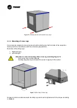
Page 16: ...sections allow the supply of major equipment in small and more easily insertable parts Sections have a base frame on which on each corner a supplied crane lug can be attached Size and weight of the s...

Page 17: ...4 Overlifting of monoblocs Size and weight of the monobloc must be determined from the data on the AHU drawing and have to be considered for the determination of the load carrying equipment and hoists...

Page 18: ...f monoblocs for monoblocs 3 3 Overlifting of AHU sections with crane lugs Chapter 3 3 is only valid for the delivery form Delivery in parts delivery sections For overlifting of units delivered as Mono...

Page 19: ...the following weight refer to Table 1 Base frame height H mm Max section weight kg 80 1 500 100 1 500 150 4 000 200 4 000 Table 1 Base frame heights depending on the AHU weight The weight of single d...

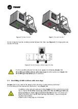
Page 20: ...es such as dampers flexible connections hoods etc must be removed before lifting see the following examples This equipment must be lifted separately on a pallet and then be reinstalled Example 1 Figur...

Page 21: ...Figure 10 Delivery section with mounted crane lugs Example 2 Figure 11 Delivery section with mounted flexible connection Figure 12 Delivery section with dismounted flexible connection...

Page 22: ...th the necessary preparations Execution of the lifting lugs 1 Right side type 2 Left side type Attention to correct mounting of the crane lug according Figure 14 blunt corner has to point upwards bend...

Page 23: ...ugs The load carrying equipment must not run over the operating side of the AHU but it must run over the opening or the front side of the AHU Figure 16 The force effect has to take place uniformly acr...

Page 24: ...ing of AHU sections with crane lugs is only valid for the delivery form Monobloc For overlifting of units delivered as Delivery in parts delivery sections see chapter 3 3 Overlifting of AHU sections w...

Page 25: ...for the lifting operation Two three or more holes per side of the monobloc are available according to the length and weight of the unit As a consequence two or more tubes rods can be used The determi...

Page 26: ...ipment In addition to the actions mentioned in this chapter 3 4 the actions according to chapter 3 5 Further necessary actions for the overlifting of both delivery sec tions on crane lugs as well as m...

Page 27: ...llowed to be knotted The load carrying equipment must be secured against slipping off After a slow lifting from the floor for a few centimeters the correct course of the load carrying equipment as wel...

Page 28: ...th a higher humidity under the nylon packaging is present e g white rust may be formed within a short time on galvanized surfaces It can further arise an exces sively high temperature under the packag...

Page 29: ...irec tion or uneven surfaces Figure 24 Solid foundation and strip foundation The AHU parts should be supported by underlayment specified in section 4 2 Erection The distance between these underlayment...

Page 30: ...ether the AHU is floorstanding heightened e g on a scaffold or sus pended from the ceiling the easy assembling and maintenance of the unit has always to be guaranteed on site Depending on the erection...

Page 31: ...timum noise insulation The providers of such products indicate the respec tive design criteria For the weight specifications see the technical data sheet For standard units without feet the maximum al...

Page 32: ...Treatment of GfK air washer and plastic parts Thermoplastics are compared with steel impact and shock sensitive At low temperatures an addi tional brittleness exists Please treat the pieces of fiberg...

Page 33: ...e suspension can consist only of transverse profiles transversely to the air flow as shown in Figure 31 or of transverse profiles with additional longitudinal profiles longitudinal to the air flow see...

Page 34: ...Figure 31 Suspension with transverse profiles Figure 32 Suspension with longitudinal and transverse profiles...

Page 35: ...act assembling position it can be moved by a rod leverage Use the rod only on the base frame profile Remove external panels at butt joints For aligning and connecting the delivery sections the externa...

Page 36: ...lying the sealing strip For roof units as well as at device separations directly before or after a wet area e g cooler hu midifier air washer special actions for sealing the AHU must be carried out by...

Page 37: ...n of the AHU cases A B and C as described below can be differ entiated Case A unit height 610 mm Screw the internal panels screw spacing minimum 305 mm Figure 41 Hexagon bolt with nut M6x16 Figure 42...

Page 38: ...rames 2 Internal mounted connection angles and frames are not accessible and or the sections are not properly aligned Connection between the internal panels as described in case A must be carried out...

Page 39: ...ssembly of delivery sections Bring the delivery sections in the exact mounting position and push them together as near as pos sible The screw holes on the flanges have to lie opposite now Moving deliv...

Page 40: ...frame and panels For the tightness at least every second hole bolt spacing 305mm shall be used After placing all the screws loosely they shall be tightened starting with the base frame in two stages r...

Page 41: ...r washer special actions for sealing the AHU must be carried out 1 The sealing agent Sikaflex has to be applied instead of the sealing strip across the whole flange of the unit 5 mm from the inner edg...

Page 42: ...ing conditions are expected or wet cleaning is planned Figure 62 Sealing surfaces Figure 63 Sealing the frontal joints Only careful sealing secures the long tightness of the unit For roof units also t...

Page 43: ...tion of engines pumps electric heaters sensors etc TRANE loosely supplies ma terial for cable glands Figure 71 which must be installed properly The following procedure is recommended 1 Drilling throug...

Page 44: ...Figure 70 Screwing Figure 71 Cable gland A drilling with the diameter for the corresponding screwing see Table 3 column 2 is sufficient for the insertion of cables into a cabinet or a single walled ho...

Page 45: ...position see Figure 74 Figure 73 Door open Figure 74 Door closed not locked Doors which allow access to the fan section are equipped with a door lock Figure 75 shows the lock in the position locked o...

Page 46: ...ent of the door panel position Because of the handling of AHU sections the position of the door panel can move see Figure 79 Due to the inclination of the door panel of the EU hinged doors problems ca...

Page 47: ...ble prefilters are supplied loose and must be in stalled on site Ensure proper insertion of the filter media the bound filter media side on the unclean air side During the installation it must be note...

Page 48: ...Figure 83 Pulling out the filters Figure 84 Pull out tool...

Page 49: ...removable bag filters with clamping mechanism When inserting and fixing the laterally removable bag filters with clamping mechanism has to be proceeded cautiously so as not to damage them The install...

Page 50: ...e assembly of the filter is done through the filter fixer supplied loose as shown in Figure 92 up to Figure 95 Figure 92 Attaching the brackets Figure 93 Inserting the filter cell Figure 94 Inserting...

Page 51: ...els 5 6 Hygienic AHU s After assembly all grooves and joints at the connection positions must be sealed with the sup plied sealing agent In case of exchange of components sealing must be restored Acce...

Page 52: ...d the transmission of vibrations and longitudinal expansion between the device and the piping system must be safely prevented The piping of the heat exchanger should hinder a for maintenance required...

Page 53: ...ontrol using a straight through valve this connection avoids unequal temperature profiles in that way air heating or cooling is quite uniform along the coil surface Figure 99 Hydraulic connection sche...

Page 54: ...ttom inlet Top outlet Figure 102 Plate heat exchangers for refrigeration circuits Application of plastic water tubes is not allowed because refrigerant and there fore also plate heat exchanger may rea...

Page 55: ...s heated to 50 60 C 100 ppm if the water is heated to 70 80 C 6 2 Connection of indirect adiabatic cooling ETA PAC AHU s are equipped with an indirect adiabatic cooling device Carry out connection to...

Page 56: ...e heights H1 H2 and H3 can be determined from the maximum negative pressure p and max imum pressure p in the section of the siphon or be determined by the information on the technical data sheet as fo...

Page 57: ...de mounting position the siphon body has to be in stalled so that the direction of the arrow see Figure 107 corresponds to the flow direction Pa suction side Pa pressure side Figure 107 Observe the mo...

Page 58: ...work must be executed tension and torsion free To prevent structure borne sound transmission is an intermediary flexible connector recom mended with at least 140 mm width It shall be installed unstra...

Page 59: ...nal regulations such as the Low Voltage Directive and the requirements of electromagnetic compatibility of national legislation and the requirements of the local electricity provider For systems which...

Page 60: ...s designed for direct start in each stage These motors are not suitable for frequency converter A frequency converter destroys the motor winding For CCEB units the following on site equipment is requi...

Page 61: ...ow it works For single speed three phase AC motors 3 temperature sensors are installed in se ries on the exhaust air side of the motor in the winding head At 135 C a sharp increase of re sistance occu...

Page 62: ...Figure 113 Wiring diagram for thermal contacts ETA AHU Are as standard equipped with circuit protection switch and frequency converters When the motor is equipped with a PTC it is connected to the te...

Page 63: ...on which is signed by an arrow for plug fan refer to Figure 115 for fan with housing refer to Figure 116 Before connecting the motor check the rotating field of mains connection with a suitable device...

Page 64: ...sup ply This means that every single AHU must be equipped with such a repair switch Requirements according to DIN VDE 0660 and IEC 947 3 on a repair switch in RED YELLOW execution 1 Is used as a repa...

Page 65: ...4 Variable frequency controlled drives VFD frequency converters If the frequency converter is supplied from someone else then TRANE please note the following points to ensure proper operation Suitabi...

Page 66: ...eliminators etc close to electric heater may become damaged or even catch fire Subsequent damages up to fire spread to the building are possible In order to avoid the above mentioned risks TRANE prov...

Page 67: ...Figure 121 the control engineering has also to ensure that the elec tric heater can only start its operation when the fan is running If in case of main power failure for example lightning stroke this...

Page 68: ...e operation temperature min 110 C for example silicone Teflon or glass fiber insulated cables Connection scheme for electric heater according to the specified safety concept as minimum re quirement Fi...

Page 69: ...ive fan motors The switches are to connect as below described If no differential pressure switches are included in the delivery of TRANE shown in the technical data sheet then another appropriate on s...

Page 70: ...ghting must be provided and separated from the power supply for the control cabinet This ensures that the light also can be switched on during repair work despite repair switch is switched off prerequ...

Page 71: ...parameters The frequency converter must be configured if not done by TRANE please refer to technical data sheet parameterization using the following Table 6 respectively the provided manufacturer s op...

Page 72: ...30 s 3 42 Speed decrease after stop 1 30 s 4 Limits Warnings 4 10 Motor rotation direction 0 Only clockwise 4 12 Minimum frequency 15 Hz 4 14 Maximum frequency Hz According to AHU data sheet Max Hz m...

Page 73: ...essure Pa Air density kg m The corresponding K factor of the fan is shown in the fan motor data sheet or on the technical data sheet provided by TRANE The air density at the measuring point is to set...

Page 74: ......

Page 75: ...ocessing the pressure signal in other devices Devices from other manufacturers may require a conversion of the K value Therefore always ask for the formula which the device is using 8 1 3 Heat exchang...

Page 76: ...is coming out Close drain and vent valve and open steam valve fully Check regularly vent valve during operation Attention For a temporary shutdown of the system because of frost and corrosion is to av...

Page 77: ...ating valve Check the right set with a manometer The bleed off quantity is to be setup at the bleed off valve Recommended setting thumb Bleed off rate evaporation rate On request we will advise you in...

Page 78: ...acuum It is essential that the glide of refrigerant blends as R407C is carefully considered when adjust ing superheat controls Air inlet and thus the entry of humidity into the refrigeration circuit m...

Page 79: ...refrigerants can also have narcotic effect In case of high refrigerant concentration e g tube leakage the technical room the room must be evacuated immediately Enter only after adequate room ventilati...

Page 80: ...e technical data sheet Remedy By replacing or adjusting the pulleys the airflow can be increased Attention Increase the fan speed only to the extent that the motor rated current is not exceed ed If th...

Page 81: ...lley 1 Decrease the belt tension 2 Open the over the disk circumference distributed screws position see Figure 128 3 Twist the outer ring the outer rings for pulleys with 2 slots to the desired diamet...

Page 82: ...per handling of sol vents and cleaning agents and no liability for mechanical damage Solvents and cleaning agents may not contain alcohol for use on coated surfaces In order to avoid corrosion in case...

Page 83: ...pillow block bearings annually must be lubricated with adverse operating conditions according to the following Table 8 with lithium soap grease see Table 9 After three lubricate the bearings must be r...

Page 84: ...ation please refer to operating instructions of motor manufac turer After three re lubrications the bearings must be dismounted cleaned and greased again For lubrication intervals under normal operati...

Page 85: ...s 1 Slippage pulley too small overloading damaged disc eccentricity wobble Figure 131 Figure 131 Unfavourable operating conditions 2 Disc worn grooved not uniform dust dirt moisture humidity Figure 13...

Page 86: ...to maintain the alignment of the discs accordingly Figure 134 and Table 11 This should be checked after each tensioning with a straight edge Figure 134 Adjustment of pulleys Pulley diameter dd1 dd2 i...

Page 87: ...irst time after about 10 hours Belt tension The correct tension of the belt is obtained if you have the same data as calculated separate ly for each drive The necessary information to tension new and...

Page 88: ...so far that the old belt can be removed Cleaned before putting the new belt pulleys and check for damage and wear Never push the new belt with a tool on the pulley to avoid damage which shorten the li...

Page 89: ...Cleaning Dirty filters dismount tapping suck off with a vacuum cleaner or clean it with air pressure max 5 bar Wash the filter in max 35 C warm water with mild commercial detergent then rinse thor ou...

Page 90: ...hrough the filter material to the outside Possibly add to the water a little bit de tergent Let the clean filter bags drain well they can be remounted wet and immediately put back into service Clean a...

Page 91: ...hall be check for dust contamination debris and cleaned if necessary The piping is to check for leaks Cleaning Cleaning is carried out in the mounted state with a strong vacuum cleaner from the dust a...

Page 92: ...ken see chapter 9 10 Refrigeration circuit 9 4 3 Electric Heater When working on the electric heater refer to instructions in chapter 2 Safety instruc tions Check electric heaters for dirt and corrosi...

Page 93: ...high pressure water Check the bleed of valve settings and proper function Check pump piping for leaks Check hoses for cracks replace if necessary Check that hose clamps are tight 9 5 3 Steam humidifie...

Page 94: ...ilicone spray if necessary Warning Gears cannot be treated with organic oils Check linkages tighten the screws if necessary 9 7 Sound attenuators The Silencers are basically maintenance free In the co...

Page 95: ...g Clean the drain pan and check the siphon Fill the siphon if necessary Fins cleaned by o Compressed air against the air flow direction or o Spraying with low pressure water if required add household...

Page 96: ...econd memory bloc is reachable when the wall between the memory blocs is pulled out Therefore are two handle holes on the upper half 8 The memory blocs should be cleaned with water with less than 20 b...

Page 97: ...in the oil Too much refrigerant in the oil causes a dilution of the oil resulting in a loss of viscosity leading to reduced lubrication of all moving parts To start the compressor manually it has to...

Page 98: ...ssor at the restart Liquid hammering can cause damage of the compressor Therefore the annual replacement of the battery is recommended for safety reasons 9 10 3 Inspection Inspection work may be carri...

Page 99: ...nd VDI6022 part 1 In chapter 5 of VDI 6022 part 1 you can find detailed requests on opera tion and maintenance TRANE recommends as cleaning agent Allrain or Multirain as disinfectant Sanosil or Sanira...

Page 100: ...Frost protection X Ch Cl Drain pan X Ch Cl Droplet eliminator X Ch Steam coil X Electric heater Ch Cl E heater X 9 4 3 Electric Heater Check e heater section for thermal damages after every mains supp...

Page 101: ...143 Sound data information 11 ATEX units The ignition hazard assessment was performed according to EN 13463 1 2009 and EN 1127 1 2011 Applied protection EN 13463 5 2011 Protection by constructional s...

Page 102: ...ixture Even in rare malfunctions very high 20 2 D Dust gas mixture Even with the usu al malfunctions high 21 3 D Dust gas mixture In normal operation normal 22 Table 13 AHU categories Classification a...

Page 103: ...allation in Zone 2 Equipment in this category provides in normal operation the required level of security II 2 G c T3 inside The AHU are designed for processing and transport of explosive atmospheres...

Page 104: ...re shall not exceed 20 C to 60 C An atmosphere with pressures from 0 8 bar to 1 1 bar shall be present in the environment of the AHU 11 3 Information for commissioning maintenance and repair 11 3 1 Fo...

Page 105: ...g on the amount of dust from dust 11 3 5 Heat exchangers steam humidifiers The in the data sheet indicated heat exchange medium temperature and the steam humidifier surface temperature shall not be ex...

Page 106: ...installation site The casing can be disassembled relatively easy Disassembly of the casing Disassembly of the external panels and removal of the insulation Loosening of the screw connections Loosening...

Page 107: ...uropean Waste Code Casing panels built in components base frames heat exchangers VZ and VZB sheet metal 170405 Stainless steel 170405 Aluminium 170402 Copper tube 170401 Copper cable Copper cable 1704...

Page 108: ...he position on the foundation 31 Figure 28 Suspension of ceiling units 32 Figure 29 Air washer with both sides feet 32 Figure 30 Comfort compound 33 Figure 31 Suspension with transverse profiles 34 Fi...

Page 109: ...h a pipe wrench 52 Figure 98 Heat exchanger connection 53 Figure 99 Hydraulic connection scheme 53 Figure 100 Drain valve 53 Figure 101 Vent valve 53 Figure 102 Plate heat exchangers for refrigeration...

Page 110: ...tion of the sensor 96 Figure 143 Sound data information 101 Figure 144 Lifting with chain hoist 106 Figure 145 Securing with belt 106 Table index Table 1 Base frame heights depending on the AHU weight...

Page 111: ...Trane offers a broad portfolio of ad vanced controls and HVAC systems comprehensive building services and parts For more information visit www Trane com Trane has a policy of continuous product and p...

Reviews: