


60
BAS-SVX40K-EN
Establishing an Air-Fi® Network
When all aspects of hardware installation are complete, you are ready to power up the system and
establish the wireless network. Before powering up, ensure that all of the procedures described in
and
“WCS-SB/SD Installation,” p. 35
have been completed.
Best Practice:
Set rotary addresses on each controller before applying power. Power up all devices in
the network at the same time. If you are unable to do this, power them up in the following order:
1. All WCIs.
2. All unit controllers: UC210, UC400, UC600, BCI-I, BCI-R, BCI2-I, BCI2-R, Symbio™ 21/210e,
Symbio™ 400/500, Symbio™ 700, Symbio™ 800.
3. The Tracer SC (always set rotary address before applying power).
4. WCSs, if present.
Note:
If the coordinator WCI is powered up 1 hour or more before the other devices on the network,
then you must open the network manually or with Tracer TU.
When applying Air-Fi® Wireless sensors with hardwired BACnet network communication (BACnet
MS/TP or BACnet/IP), refer to
“Installing Air-Fi Wireless Sensors with BACnet MS/TP or BACnet/
section.
WCI LEDs and Buttons
Before establishing a network, you should be familiar with the layout of the WCI board, the behavior of
its LEDs, and the function of its buttons. The WCI board contains two buttons and several LEDs. The
LEDs relevant to network formation are shown in the following figures.
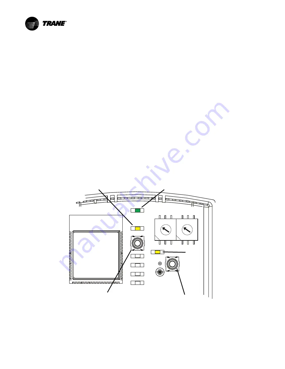
Figure 42.
LEDs and buttons related to network formation (WCI version 1 and 2 built prior to
2019)
NWK
CRD
RX LINK
TX LINK
DIAG
PWR
OPEN NET
1
2 3 4
5
6
7
8
9
0
1
2 3 4
5
6
7
8
9
0
The green NWK LED:
The yellow CRD LED
OPEN NET
LED
OPEN NET
button
The START button


