


18-CD31D1-3
9
Installer’s Guide
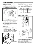
2. The return air filter and rack are shipped in either the
bottom or side location. Remove the filter and filter
rack by first turning the two latches on the blower door
and tilting the door forward to remove. Remove the
filter by sliding it out of the rack. Compress the spring
loaded filter rack to disengage the retaining pins/
screws from the furnace sides and slide the filter rack
out.
The filter rails are spring loaded for automatic adjust-
ment to allow standard size, locally obtainable replace-
ment filters. The filter rack itself slides to adjust to the
required width needed for bottom or side return (See
Figure 14).
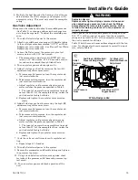
3. For upflow side return installations, remove the
insulation around the opening in the blower compart-
ment.
4. The side panels of the upflow furnace include locating
notches that are used as guides for cutting an open-
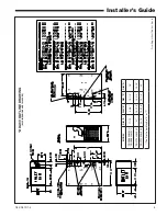
ing for return air, refer to Figure 12 and the outline
drawing on page 4 for duct connection dimensions for
various furnaces.
S
WARNING
!
TO PREVENT INJURY OR DEATH DUE TO CONTACT
WITH MOVING PARTS, TURN THE POWER TO THE
FURNACE OFF BEFORE SERVICING FILTERS.
5. The bottom panel of the upflow furnace must be re-
moved for bottom return air. After removing the filter
and filter rack, lay the furnace on its back. Remove the
two 5/16" hex screws securing the front of the bottom
channel to the cabinet. Rotate the channel downward
(or remove by lowering the front edge of the channel
and pulling forward). Slide the bottom return air panel
out of the cabinet. Rotate the front channel to its origi-
nal position and reinstall the two 5/16” screws.
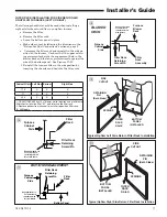
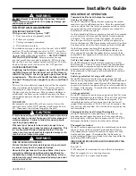
6. If a 3/4" flange is to be used for attaching the air inlet
duct, add to cut where indicated by dotted lines in
Figure 12. Cut corners diagonally and bend outward to
form flange.
7. If flanges are not required, and a filter frame is in-
stalled, cut between locating notches (See Figure 13).
8.
Upflow Furnaces:
a filter rack is factory supplied for
bottom or side return. Use the filter rack on either side
or on the bottom if the filter is to be used within the
furnace cabinet.
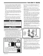
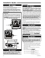
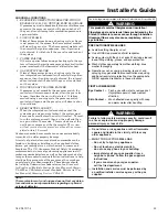
When the upflow furnace is installed in the horizontal
right or left application and a return duct is attached
to the top side as shown in Figure 11, remove the filter
from the furnace and install in a remote location.
Do not install the filter in the return duct directly
above the furnace in horizontal applications.
When the upflow furnace is installed in the horizontal
right or left application and a close coupled (less than
36") return duct is attached to the bottom side of the
furnace as shown in Figure 11, securely attach a 1/2"
mesh metal hardware cloth protective screen to the
inside bottom of the filter grill
to prevent personal
injury from contacting moving parts when reach-
ing into the return opening to replace the filter.
Close coupled (less than 36") return (filter directly
beneath bottom side return) is not recommended due to
noise considerations.
Downflow Furnaces:
Brackets are factory supplied
to mount filters in the return air duct work.
9. Connect the duct work to the furnace. See Outline
Drawing for supply and return duct size and location.
S
WARNING
!
Do not install the filter in the return duct directly above the
furnace in horizontal applications. Install the filter remotely.
Installing the filter directly above the furnace in horizontal
applications may cause property damage, serious injury or
death.
FILTER
REMOVE FILTER FROM UPFLOW
FURNACE WHEN RETURN DUCT IS
ATTACHED TO FURNACE TOP SIDE
(HORIZONTAL LEFT OR RIGHT AP-
PLICATIONS) AS SHOWN.
Close coupled (less than 36")
return (filter directly beneath bottom
side return) not recommended due to
noise considerations. If used, securely
attach 1/2" mesh metal hardware cloth
protective screen to the inside bottom
of filter grill.
Flexible duct connectors are recommended to connect
both supply and return air ducts to the furnace.
If only the front of the furnace is accessible, it is recom-
mended that both supply and return air plenums are
removable.
10. When replacing a furnace, old duct work should be
cleaned out. Thin cloths should be placed over the
registers and the furnace fan should be run for 10 min-
utes. Don’t forget to remove the cloths before you start
the furnace.
11.
The horizontal installation of the upflow furnace
requires an external filter section. Do NOT use the
bottom return filter within the furnace. Filter kits
are available for horizontal applications.
Q
*
SEE OUTLINE DRAWING
W
LOCATING
NOTCHES
PROVIDED
FOR SIDE
RETURN
CUTOUT
*
*
*
*
CUT OUT
FOR
SIDE
FILTER
FRONT
of Furnace