82
TRAK Machine Tools
Southwestern Industries, Inc.
ProtoTRAK SMX, K2, K3 & K4 & Retrofit Safety, Installation, Maintenance, Service and Parts List Manual
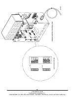
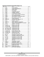
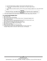
Parts List K Mill Sensor Assembly (Figure 27)
Item
P/N
DESCRIPTION
1
M250C
SENSOR - ALL TRAK PRODUCTS
2
M5
M-5 BASE
3
LDCEL-C
LOADCELL - M250C
4
M5 HDWR
HARDWARE - M5 BASE
5
16023-1
BRACKET-SENSOR X-AXIS (K2)
6
21511
EXTENSION
7
14600
BAR-RUN Y-AXIS
8
13384-4
BRACKET-SENSOR Y-AXIS (K2)
9
15346
CHIP SCRAPER-M250C
10
16023-2
BRACKET-SENSOR X-AXIS (K3 & K4)
11
13777-1
BRACKET UNIVERSAL BR17-RY MODIFIED (K3 & K4)
i01117
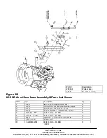
5.1.7 Glass Scale Replacement
5.1.7.1 Remove the X, Y or Z Glass Scale
1.
Unplug the glass scale connector from the cable breakout box.
2.
Unbolt the reader head of the glass scale from its mounting surface.
3.
Unbolt the glass scale enclosure from the table on X or the mounting spar on Y.
4.
Install the head alignment bracket that came with the replacement scale to this scale to secure it for shipping
back to SWI. Failure to do this may cause the glass scale to get damaged during shipment. The head
alignment bracket secures the reader head so it cannot move and damage the glass in the scale.
Note: 1
st
align the reader head on the new scale before removing it to fasten the old scale.
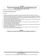
CAUTION!
Once the head alignment bracket is installed, do not traverse the axis or the reader
head will break.
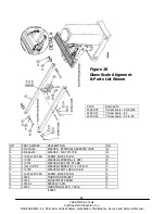
5.1.7.2 Install the X or Y Replacement Scale
CAUTION!
If the scale is not long enough for the table, it will break when the machine is
traversed past the scale travel.
1.
Mount the scale to the back of the table or Y-axis mounting spar.
2.
Align the sale so that it is /- 0.005" end to end.
Notes:
For the Y-axis, the mounting spar should already be aligned. It must be parallel to the Y-axis travel /-
.005" end to end both horizontally and vertically. The mounting spar can be aligned in and out by the use of the
adjustment screw.
3.
Line the reader head up with the mounting holes on the back of the saddle for the X-axis or the bracket on the
Y-axis.
4.
Install the reader head bolts but leave them loose.
5.
Use the jackscrews on the reader head to compensate for some gap between the reader head and the reader
head mounting bracket. Leave the alignment brackets attached to the reader head. This bracket assures the
reader head is aligned to the glass scale.
6.
Tighten each jackscrew until it touches the bracket and then back it off 0.001” or 0.002”. Use a feeler gage to
set the gap.
7.
Tightening the reader head mounting screws. This ensures the reader head is aligned within a few thousandths.
8.
Remove the shipping bracket that fixes the reader head to the scale for shipping.

