142
TRAK Machine Tools
Southwestern Industries, Inc.
ProtoTRAK SMX, K2, K3 & K4 & Retrofit Safety, Installation, Maintenance, Service and Parts List Manual
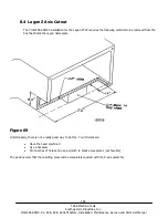
Caution!
Binding in the quill travel will impair system performance and may
damage the ball screw assembly.
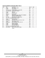
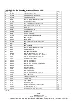
19
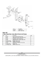
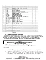
98029A036
WASHER-FINISHED FLAT-CASE HARDENED STL
EA
1
20
3/4-16 51Z
NUT-HEX JAM-STL-ZINC-GRADE 2
EA
1
21
16364-3
SCREW 3/8-24 BRKT BALLNUT MOUNTING
EA
1
22
16739
JACKSCREW NUT
EA
1
23
14932
WASHER-LOWER BOLT
EA
2
24
15759
WASHER-1/4 HARD BLK OX 1/8 THK
EA
2
25
16355-3
SCREW M10.-1.0. BRKT. BALLNUT MOUNTING
EA
1
26
16365
SPACER CENTERING HOLE
EA
1
27
16212-175
COUPLING SOCKET HEAD
EA
2
28
1/4-20 56Z
NUT-NYLON LOCK-STL-ZINC
EA
2
29
16357-2
BRACKET BALLNUT FORK EXT SUPERMAX 16VS
EA
1
30
1/2-13X1 1/2 25B SCREW-SHCS-STL-BO
EA
2
31
1/4-20X1 3/4 25B SCREW-SHCS-STL-BO
EA
2
32
1/4-20X1 40B
SCREW-SOC SET-STL-BO-CUP
EA
4
33
1/4-20X3/4 25B
SCREW-SHCS-STL-BO
EA
2
34
1/4-20X3/8 40B
SCREW-SOC SET-STL-BO-CUP
EA
4
35
3/8-16 50B
NUT-HEX-STL-BO
EA
1
36
3/8 70P
WASHER-FLAT USS-STL-BO
EA
1
37
3/8 73B
WASHER-SPLIT LOCK-STL-BO
EA
2
38
16210-1
POSITIONER LOCATOR
EA
2
39
M6-1.0X25 25B
SCREW-SHCS-STL-BO
EA
2
40
M10 73B
WASHER-SPLIT LOCK-STL-BO
EA
1
41
16740
COUPLING SOCKET HEAD
EA
1
42
¼-20 x 1 1/4 25B SCREW-SHCS-STL-BO
EA
4
43
3/8-24 x 2 ¼ 25B SCREW-SHCS-STL-BO
EA
1
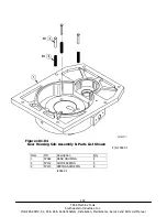
i25000-XX
8.2 Installation of the Ball Screw
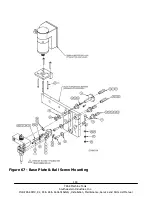
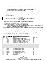
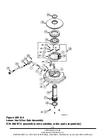
1. Install the ball screw assembly as shown in Figure 67. Run the quill up and down over its full travel at each step to
ensure that there is no binding. Adjust as necessary. You can mount a dial indicator on the top of the table, locating off
the ballscrew. Move the knee up and down and tram in the ballscrew from front to back with the leveling nuts.
Note: Loosely install the ball screw at first, and then attach the fork with the quill near the top of its travel.
8.3 Installation of the Motor and Remaining Components
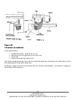
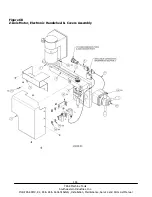
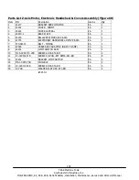
See figure 67 & 68
1. Install the motor mounting bracket to the top of the base plate.
2.
Install the motor to this bracket. Install the belt between the pulleys and tension it by sliding the motor
away from the head. Tighten the 4 screws that hold the motor down.
3.
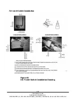
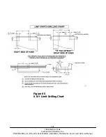
Install the limit switch brackets that hold the upper and lower quill limit switches in place. Manually move
the ballscrew up until you reach a hard stop. Now move the ballscrew down 1 turn of the ballscrew and set
the upper limit switch. The brackets are slotted to allow up and down adjustment. Move the ballscrew

