Tracker Off-Road EViS 2020 Repair And Service Manual Download Page 102

B

88

Repair and Service Manual

REAR AXLE AND SUSPENSION

Read all of SAFETY and this section before attempting any procedure. Pay particular attention to Notices, Cautions, Warnings and Dangers.

10002660

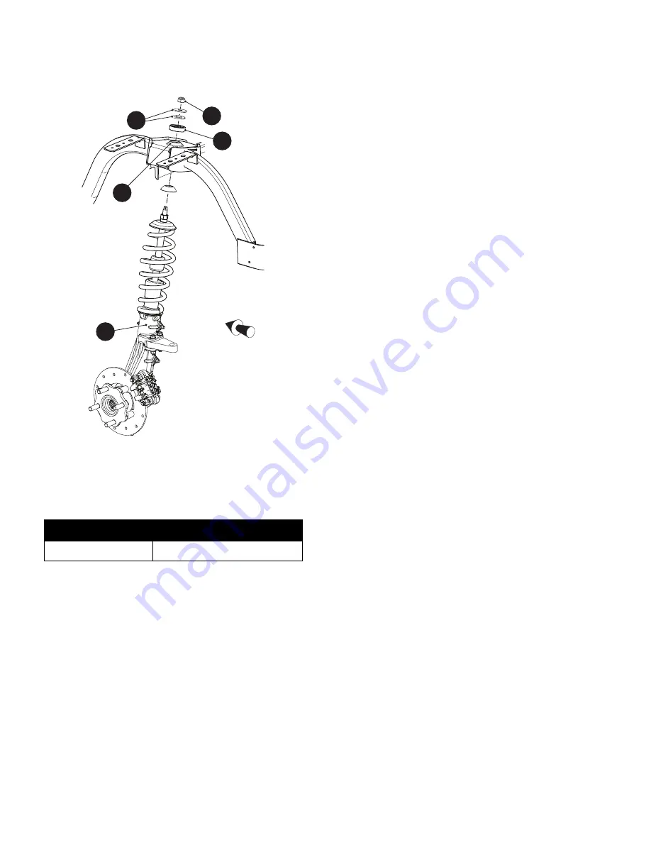
Fig. 5  Strut Assembly

Assemble in the reverse order of removal using new lock 

nuts.
Tighten the lock nut to the torque values specified below.

Strut Assembly Maintenance Items

The following maintenance procedures are identical to 

the front strut assembly procedures (See FRONT SUS- 

PENSION on page 53):

Lower Ball Joint Replacement

Wheel Bearing Replacement

Strut Replacement

Item

Torque Specification

27

14 - 16 ft. lbs. (19 - 47 Nm)

Front of Vehicle

27

29

28

13

24

Summary of Contents for EViS 2020

Page 1: ...REPAIR AND SERVICE MANUAL TRACKER EViS 10002660 C Revised Dec 2019 Issued Aug 2019...

Page 2: ...ove the vehicle from one location to another location If the vehicle is used in a commercial environment signs must be in position to inform of possible conditions that can be dangerous Examples shown...

Page 3: ...ts in this manual without obligation to include these changes on units sold previously The information contained in this manual may be revised periodically by the manufacturer and therefore is subject...

Page 4: ...ower from the battery pack and eventually drain the batteries if power is not restored in a timely manner As with all electric vehicles the batteries must be checked and recharged as required or at a...

Page 5: ...vehicle is designed and manufactured for off road use It does not conform to Federal Motor Vehicle Safety Stan dards and is not equipped for operation on public streets Some communities may permit th...

Page 6: ...sing wheel chocks and safety stands Never get under a vehicle that is supported by a jack Lift the vehicle in accordance with the manufacturer s instructions Never attempt to maintain a vehicle in an...

Page 7: ...ICLE CLEANING AND CARE 2 VEHICLE CARE PRODUCTS 3 OPS CANOPY TOP AND WINDSHIELD 3 TRANSPORTING VEHICLE 3 EMERGENCY ELECTRIC PARK BRAKE RELEASE 3 TOWING A TRAILER 4 PROLONGED STORAGE 4 HARDWARE 4 TORQUE...

Page 8: ...yte Level and Water 16 Cleaning Batteries 17 Prolonged Storage 17 Battery Charging 18 AC Voltage 18 FAULT TESTING 18 Hydrometer 19 Using Hydrometer 19 BATTERY CHARGER 20 Charger Description 20 Portabl...

Page 9: ...rake Pads Replacement 37 Rotor Replacement 38 BLEEDING AND FLUSHING 38 Bleeding 38 Bleeding Sequence 39 Flushing 39 BRAKE PEDAL REMOVAL AND INSTALLATION 40 ELECTRICAL VOLTAGE TESTING FOR BATTERIES 47...

Page 10: ...7 Front Strut Assembly Replacement 57 Control Arm Assembly Replacement 58 Lower Ball Joint Replacement 58 Wheel Bearing Replacement 59 Strut Replacement 60 FRONT AXLE 61 CV Shaft Replacement 61 CV Joi...

Page 11: ...acement 78 Rear Seat Belt Buckle Replacement 78 UPPER OPERATOR PROTECTION SYSTEM 80 Upper OPS Frame Removal and Installation 80 LOWER OPERATOR PROTECTION SYSTEM 81 Brush Guard Removal and Installation...

Page 12: ...119 Key Switch Testing 119 State of Charge SOC Meter Testing 120 Electronic Speed Controller Solenoid Testing 120 Temperature Sensor Testing 121 Electronic Speed Sensor Testing 121 AC Motor Bench Tes...

Page 13: ...xi Repair and Service Manual Notes 10002660...

Page 14: ...xii Repair and Service Manual Notes 10002660...

Page 15: ...vehicle at full throttle for more than 4 5 seconds while vehicle is in a no load condition all 4 wheels off of the ground It is in the best interest of both vehicle owner and servic ing dealer to care...

Page 16: ...h caused from driving a vehicle with an improperly operating brake sys tem the braking system must be properly main tained All driving brake tests must be done in a safe location with regard for the s...

Page 17: ...ect against large falling objects such as trees or heavy limbs The optional windshield deflects oncoming wind from occupants but will not protect against flying objects and tree limbs The optional can...

Page 18: ...ring periods of storage the batteries must be main tained to prevent discharge During cold conditions the batteries must be fully charged to prevent the possibility of freezing A fully charged battery...

Page 19: ...12G02 ALL TORQUE FIGURES ARE IN FT LBS Nm BOLT SIZE Grade 2 1 4 5 16 3 8 7 16 1 2 9 16 5 8 3 4 7 8 1 Unless otherwise noted in text tighten all hardware in accordance with this chart This chart specif...

Page 20: ...nd Service Manual GENERAL INFORMATION AND ROUTINE MAINTENANCE Read all of SAFETY and this section before attempting any procedure Pay particular attention to Notices Cautions Warnings and Dangers Note...

Page 21: ...e vehicle Changes to the weight distribution or the center of gravity decreases the stability of the vehicle and can cause it to easily roll over GENERAL MAINTENANCE Always use correct service proce d...

Page 22: ...ls which could result in an explosion Make sure to fill the batteries to a level of 1 2 inch 13 mm above the plates Electrolyte more than 1 2 inch 13 mm above the plates can cause a spill from the bat...

Page 23: ...the jack and test the stability of the vehicle on jack stands by gently rocking the vehicle 5 The jack can be left under the center front of the frame while the front end of the vehicle is on the jack...

Page 24: ...10 Repair and Service Manual SAFETY Read all of SAFETY and this section before attempting any procedure Pay particular attention to Notices Cautions Warnings and Dangers Notes 10002660...

Page 25: ...ocket 7 16 1 Socket 13 mm Wrench 7 16 1 Wrench 13 mm Ratchet 1 Torque Wrench ft lbs 1 1 To access the accelerator pedal 1 remove two bolts 3 washers 4 and nuts 7 that secure the cover 5 to the mountin...

Page 26: ...12 Repair and Service Manual ACCELERATOR Read all of SAFETY and this section before attempting any procedure Pay particular attention to Notices Cautions Warnings and Dangers Notes 10002660...

Page 27: ...es when add ing water or charging batteries Any electrolyte spills should be neutralized with a solution of 1 4 cup 60 ml sodium bicarbonate baking soda dissolved in 1 1 2 gallons 6 liters of water an...

Page 28: ...nch 1 2 1 Insulated Wrench 9 16 1 Insulated Socket 1 2 1 Insulated Socket 9 16 1 Ratchet 1 Battery Carrier 1 Torque Wrench ft lbs 1 Torque Wrench in lbs 1 Putty Knife 1 Wire Brush 1 Terminal Spreader...

Page 29: ...ion from the battery terminals or the wire terminals with a solution of sodium bicarbonate baking soda and brush 6 Connect the battery wires as shown Ref Fig 2 Be sure that all battery terminals are i...

Page 30: ...e that results from the charging cycle Fig 4 Correct Electrolyte Level Do not overfill batteries The charging cycle will increase electro lyte volume and force it out of the battery and damage surroun...

Page 31: ...n batteries for minimum of three minutes Use a soft bristle brush or cloth to clean the tops of the batteries to remove any residue that could cause the self discharge of the battery Rinse the entire...

Page 32: ...cts NOTICE In some portable chargers an audible rat tle is present in the body of the charger DC plug This rattle is caused by an internal magnet within the charger plug The magnet is part of the inte...

Page 33: ...yes with extended flushing with clear water Contact a physician immediately Always wear a safety shield or approved safety goggles when using a hydrometer to test the elec trolyte solution Any electro...

Page 34: ...local codes and ordinances A grounded outlet is required to reduce risk of electric shock do not use ground adapters or modify the plug Do not touch uninsulated por tion of output connector or uninsu...

Page 35: ...e batteries are fully charged and the DC plug can be removed from the vehicle NOTICE Routing the DC cord through the steering wheel when charging the batteries serves as a good reminder to store the c...

Page 36: ...epair and Service Manual BATTERIES AND BATTERY CHARGER Read all of SAFETY and this section before attempting any procedure Pay particular attention to Notices Cautions Warnings and Dangers Notes 10002...

Page 37: ...nts can be replaced with a minimum of special tools Most body components are held in position with standard removable hardware nuts bolts washers and screws Some components are installed with pop riv...

Page 38: ...The gauge panel can be removed without removing the instrument panel To prevent personal injury discon nect negative battery cables before servicing vehicle Removal 1 Remove two screws 6 that secure t...

Page 39: ...out the remaining rivets 11 5 Remove cowl assembly 15 from vehicle Ref Fig 6 Assemble in the reverse order of removal using new riv ets Fig 6 Cowl Removal Removal of Headlight Grille Assembly Tool Lis...

Page 40: ...r Weldment Removal and Installation on page 82 3 Remove the rocker panels See Rocker Panel Replacement on page 24 4 Remove the cowl See Cowl Replacement on page 25 5 Remove the gauge panel See Gauge P...

Page 41: ...ETY and this section before attempting any procedure Pay particular attention to Notices Cautions Warnings and Dangers 27 Repair and Service Manual 10002660 Fig 8 Instrument Panel Rear 22 25 23 21 10...

Page 42: ...To replace either driver or passenger side panel 1 Disconnect the tail light leads from the main wiring harness 2 Drill out the two rivets 36 securing the side panel 35 to the rear fender 30 3 Remove...

Page 43: ...uring installation 2 Remove the 6 screws 42 connecting the front of the seat wrap 40 to the sides 45 3 Pull the front portion 40 of the seat wrap out of the vehicle 4 Remove the screws 46 connecting t...

Page 44: ...16 1 Wrench 9 16 1 Torque Wrench ft lbs 1 Socket 7 16 1 Socket 9 16 1 Torque Wench ft lbs 1 1 Remove the bolts 53 lock washers 52 washers 54 and nuts 51 securing rear closeout panel 50 to chassis fram...

Page 45: ...ssembly Front of Vehicle Yellow wire Cable bundle continues towards vehicle rear Winch Fairlead Plow Assembly Torque to 45 55 Nm 33 2 40 6 ft lbs Insert and bend cotter pin after inserting hook retent...

Page 46: ...hes the manufacturer of the Durashield body panels recommends the following steps be taken 1 Thoroughly clean the surface to be repaired with alcohol and allow to dry 2 Apply tape to area surrounding...

Page 47: ...33 Repair and Service Manual BODY Read all of SAFETY and this section before attempting any procedure Pay particular attention to Notices Cautions Warnings and Dangers Notes 10002660...

Page 48: ...34 Repair and Service Manual BODY Read all of SAFETY and this section before attempting any procedure Pay particular attention to Notices Cautions Warnings and Dangers Notes 10002660...

Page 49: ...ome ini tial free play and then become resistant This indicates proper performance If the brake pedal has a soft feel or loses resistance per form a brake system inspection See Brake System Inspection...

Page 50: ...r deposits formed in the cylinder bore that are due to moisture or dirt in the hydraulic system may cause wear of the cylinder bore or related parts Do not try to remove corrosion or deposits with a c...

Page 51: ...front and rear brake pads must be replaced as a full set Replace the brake pads as a full set on both wheels To remove the brake pads lift and support the vehicle See LIFTING THE VEHICLE on page 8 1...

Page 52: ...er of removal Tighten all hardware in a cross pattern to the torque values specified below Fig 4 Rotor BLEEDING AND FLUSHING Tool List Qty Shop Towels A R Hose A R Clean Container Glass 1 Brake Fluid...

Page 53: ...s air bubbles as they come out of the system and prevents air from being sucked into the system through the bleeder screw 2 Apply moderate 40 50 lbs 18 23 kg steady pressure on the brake pedal and ope...

Page 54: ...iver Flat Head 1 Allen Socket 1 4 1 Ratchet 1 Wrench 1 2 1 Socket 1 2 1 Torque Wrench ft lbs 1 1 Disconnect the master cylinder shaft from the brake pedal 8 See Master Cylinder Replacement on page 36...

Page 55: ...41 Repair and Service Manual Notes Read all of SAFETY and this section before attempting any procedure Pay particular attention to Notices Cautions Warnings and Dangers BRAKES 10002660...

Page 56: ...42 Repair and Service Manual BRAKES Read all of SAFETY and this section before attempting any procedure Pay particular attention to Notices Cautions Warnings and Dangers Notes 10002660...

Page 57: ...r attention to Notices Cautions Warnings and Dangers 43 Repair and Service Manual 10002660 ELECTRICAL Fig 1 Main Harness Routing Front of Vehicle Main Harness to Headlight Main Harness to Contactor Ma...

Page 58: ...ir and Service Manual ELECTRICAL Read all of SAFETY and this section before attempting any procedure Pay particular attention to Notices Cautions Warnings and Dangers 10002660 Fig 2 Main Harness Wirin...

Page 59: ...TRICAL Read all of SAFETY and this section before attempting any procedure Pay particular attention to Notices Cautions Warnings and Dangers 45 Repair and Service Manual 10002660 Fig 3 Electrical Sche...

Page 60: ...and Service Manual ELECTRICAL Read all of SAFETY and this section before attempting any procedure Pay particular attention to Notices Cautions Warnings and Dangers 10002660 Fig 4 Electrical Schematic...

Page 61: ...unction A faulty wire must be replaced See Faulty Wire Replacement on page 48 3 Check the condition of the 72V batteries set a Check for adequate battery volts nominal 12 VDC by setting the DVOM to 30...

Page 62: ...circuit to the ground connection Correct any interruption of electricity flow by repairing or replacing the wire or the switch or accessory Faulty Wire Replacement Replace a faulty wire with one of th...

Page 63: ...troller is a solid state unit that activates a sole noid and controls the function of the vehicle by respond ing to inputs from the rotary position sensor motor speed sensor and many other units The c...

Page 64: ...st on page 122 1 Use an insulated wrench to remove the negative B wire from the battery 2 Remove the bolts 21 and flat washers 22 Ref Fig 10 3 Remove the connectors from the controller 24 Ref Fig 10 4...

Page 65: ...olenoid 20 2 Remove the two screws 16 washers 18 and nuts 17 to remove the solenoid 20 from the rear fender Ref Fig 11 3 Mount new solenoid 20 and connect the wiring 4 Tighten the nut 17 to torque val...

Page 66: ...device is indicated Testing Battery Voltage Determine the condition of the battery set before proceed ing with any electrical testing An open voltage test is not helpful since a battery that has deter...

Page 67: ...ition and remove the key 2 Disconnect the negative battery cable using an insulated wrench 3 Remove the gauge panel See Gauge Panel Replacement on page 24 4 Disconnect the main wiring harness from the...

Page 68: ...switch 43 and push it through the front of the gauge panel 40 Ref Fig 17 Assemble in the reverse order of removal Confirm proper orientation of the switch prior to seating it completely in the gauge p...

Page 69: ...ing in elec tape And securing with cable tie Removing prior to taping also acceptable Connect red and black contactor cables to and driver side battery using nuts Red cable Yellow wire Connect red wir...

Page 70: ...56 Repair and Service Manual ELECTRICAL Read all of SAFETY and this section before attempting any procedure Pay particular attention to Notices Cautions Warnings and Dangers Notes 10002660...

Page 71: ...rol arms contain lube free bushings The tie rod ends are sealed and do not require lubrica tion The steering unit is sealed and does not require lubrica tion Front Strut Assembly Replacement Tool List...

Page 72: ...ssembly 1 5 Remove the bolt 22 flanged bushings 19 and lock nuts 23 6 To remove the control arm 21 from the vehicle Ref Fig 2 Assemble in the reverse order of removal Tighten hardware to torque values...

Page 73: ...Ring Pliers 1 Arbor Press 1 Hammer Ball Peen 1 Brass Punch 1 1 Lift and support the front of the vehicle See Lift Front of Vehicle on page 9 2 Remove the front wheel See WHEEL AND TIRE SERVICE on pag...

Page 74: ...CE on page 128 3 Remove the strut assembly See Front Strut Assem bly Replacement on page 57 4 Compress the coil spring 115 just enough to relieve the tension between the coil spring cap 112 and the co...

Page 75: ...ef Fig 1 4 Remove the cotter pin 24 castle nut 25 and flat washer 26 from the end of the front axle 27 Ref Fig 1 5 Remove the cotter pin 10 and nut 9 from the lower ball joint Ref Fig 1 6 Tap downward...

Page 76: ...1 Socket 9 16 1 Wrench 9 16 1 Torque Wrench ft lbs 1 To prevent injury caused by acci dental movement of the differential you must have a second person to help support and remove the differ ential 1 L...

Page 77: ...at this time 3 From below the steering wheel put a plastic faced hammer against the lock nut as shown Ref Fig 10 4 Pull upward on the plastic faced hammer and strike hammer sharply with a ball peen h...

Page 78: ...he steering wheel See Steering Wheel Replacement on page 63 2 Remove the four bolts 41 and lock nuts 42 that secure the steering column 40 to the frame 3 Remove the yoke bolts 44 lock washers and nuts...

Page 79: ...1 Floor Jack 1 Wheel Chocks 2 Jack Stands 2 1 Raise the front of the vehicle See Lift Front of Vehi cle on page 9 2 Remove the front wheels See WHEEL AND TIRE SERVICE on page 128 3 Remove the steerin...

Page 80: ...allation MAINTENANCE All steering and suspension components are lube free Routine examination of the tires provide indications that an alignment is required NOTICE Some maintenance items must be servi...

Page 81: ...ice Manual 10002660 Counting threads or measuring thread distance are two methods to equalize tie rod length Drive the vehicle to confirm that the steering wheel is cor rectly centered If not remove t...

Page 82: ...r and Service Manual FRONT CV SHAFT SUSPENSION AND STEERING Read all of SAFETY and this section before attempting any procedure Pay particular attention to Notices Cautions Warnings and Dangers Notes...

Page 83: ...1 Insulated Socket 9 16 1 Ratchet 1 1 Use an insulated wrench to disconnect the negative battery cable from the battery Ref Fig 2 2 Disconnect the harness from the motor brake con nector 7 3 Remove th...

Page 84: ...otor housings to help with realignment during assembly of the motor to rear axle Ref Fig 3 Fig 2 Disconnect Battery Cable Fig 3 Mark Axle and Motor Do not damage the splines when removing and installi...

Page 85: ...ferential 10 Finger tighten the bolts 11 in a cross sequence Ref Fig 4 then tighten to 25 in lbs 2 82 Nm increments of torque using the same cross sequence pattern 4 Reconnect the temperature sensor 9...

Page 86: ...rom terminals U V and W 12 Ref Fig 8 Ref Fig 9 Fig 6 Disconnect Battery Cable Fig 7 Mark Axle and Motor Do not damage the splines when removing and installing the motor to the rear axle housing 4 Disc...

Page 87: ...cross sequence pattern 4 Reconnect the temperature sensor 9 and speed sensor 8 wiring harnesses 5 Reconnect the U V and W terminals 12 Ref Fig 8 Ref Fig 9 Tighten the hardware to the torque values sp...

Page 88: ...74 Repair and Service Manual MOTOR Read all of SAFETY and this section before attempting any procedure Pay particular attention to Notices Cautions Warnings and Dangers Notes 10002660...

Page 89: ...Wrench 9 16 1 1 To remove front seat back 9 remove four screws 11 and lock washers 12 securing the seat back to the lower OPS Ref Fig 1 2 Remove the four lock nuts 8 washers 7 and bolts 6 from the sea...

Page 90: ...Buckle Removal on page 79 8 Remove the four lock nuts 35 flat washers 20 and bolts 19 to remove the seat bottom 18 Ref Fig 4 Fig 4 Seat Bottom Removal 9 Remove the bolts 42 flat washers 43 and lock nu...

Page 91: ...the rear closeout panel 4 See Rear Closeout Panel Replacement on page 30 2 Remove the bolts 36 and lock nuts that secure the footrest 24 to the armrest Ref Fig 7 3 Remove the center lock nuts 28 and b...

Page 92: ...he torque values specified below Fig 9 Front Seat Belt Buckle Removal Rear Seat Belt Buckle Replacement Tool List Qty Socket 5 8 1 Ratchet 1 Wrench 5 8 1 Torque Wrench ft lbs 1 1 Remove bolts 74 and l...

Page 93: ...FETY and this section before attempting any procedure Pay particular attention to Notices Cautions Warnings and Dangers 79 Repair and Service Manual 10002660 Fig 10 Rear Seat Belt Buckle Removal 74 73...

Page 94: ...commended Use a personal back support brace and proper lift ing technique to prevent personal injury 2 Loosen but do not remove the four bolts 84 fas tening the forward 85 and the rear 86 sections of...

Page 95: ...Socket 1 2 1 Socket 15mm 1 Ratchet 1 Wrench 1 2 1 Wrench 15mm 1 Torque Wrench ft lbs 1 1 Remove the bolts 101 and lock nuts 103 from the brush guard 100 Ref Fig 12 2 Remove the bolts 104 and lock nuts...

Page 96: ...Installation on page 81 4 Remove the seat belts See Seat Belt Removal and Installation on page 77 5 Remove the front seat belt buckle See Front Seat Belt Buckle Replacement on page 78 6 Loosen but do...

Page 97: ...83 Repair and Service Manual 10002660 Fig 14 Lower OPS Weldment Assemble in the reverse order of removal Tighten hardware to torques values specified below 110 121 122 123 124 126 125 128 129 127 128...

Page 98: ...84 Repair and Service Manual SEATING AND OPS Read all of SAFETY and this section before attempting any procedure Pay particular attention to Notices Cautions Warnings and Dangers Notes 10002660...

Page 99: ...cant SAE 80W 90 gear oil Add slowly until lubricant reaches capacity If the lubricant needs to be replaced a drain plug 12 for removing the lubricant is located at the bottom of the dif ferential hous...

Page 100: ...nt separator Ref Fig 3 13 Remove the axle 10 from the strut assembly 13 by pulling the strut assembly outward Ref Fig 2 14 Remove the CV Axle from the differential using a pry bar Fig 3 Control Arm an...

Page 101: ...se order of removal using red thread locking compound Tighten the mounting bolts to the torque values specified below REAR SUSPENSION NOTICE Hardware that is removed must always be installed in its or...

Page 102: ...ble in the reverse order of removal using new lock nuts Tighten the lock nut to the torque values specified below Strut Assembly Maintenance Items The following maintenance procedures are identical to...

Page 103: ...9 Repair and Service Manual Notes Read all of SAFETY and this section before attempting any procedure Pay particular attention to Notices Cautions Warnings and Dangers REAR AXLE AND SUSPENSION 1000266...

Page 104: ...0 Repair and Service Manual REAR AXLE AND SUSPENSION Read all of SAFETY and this section before attempting any procedure Pay particular attention to Notices Cautions Warnings and Dangers Notes 1000266...

Page 105: ...grease has accumulated in the bellows Remove the bellows and remove excess grease Insufficient lubricant in king pins tie rod ends idler bushing rack tensioner or steering box Add one shot of lubrican...

Page 106: ...3 Curtis Programmer Port Fig 4 Curtis Programmer Port Installation Connect the Molex plug to the receptacle on the face of the controller Navigation A blinking square on the left indicates the positi...

Page 107: ...Controller 0 1 0 Monitor Solenoid Coil On Off On Rear Node Select On Off On Solenoid PWM 0 100 0 Rear Controller Run Tow Switch On Off Key Switch or Charger On Off Off Economy Mode Switch On Off Off F...

Page 108: ...00 100 Controller Temp Cutback 0 100 100 Under voltage Cutback 0 100 0 Over voltage Cutback 0 100 100 Vehicle Vehicle Speed 3276 8 3276 7 0 Vehicle Odometer 0 0 10000000 0 Varies Braking Distance 0 0...

Page 109: ...version Display the controller protocol version Parameter Block Version Display controller PB version Display controller PB version Model Number Display the controller model number Display the contro...

Page 110: ...play OEM information Reconfigured Display reconfigure status Model Number Display handheld model number Serial Number Display handheld serial number Manufacturing Date Display handheld manufacture dat...

Page 111: ...ed LED flashes once to indicate that the first digit of the code will follow the yellow LED then flashes the appropri ate number of times for the first digit The red LED flashes twice to indicate that...

Page 112: ...al load on capacitor bank preventing capacitor charge 3 Check wiring 4 Check brake sensor if other faults are found 1 5 Controller Sever Undertemp Heat sink temperature below 40 C Vehicle Disabled Rai...

Page 113: ...ler system drain 4 Battery resistance to high 5 Battery disconnected while driving 6 See Monitor menu Battery capacitor voltage 7 Blown B fuse or main contactor did not close 2 4 Overvoltage Cutback C...

Page 114: ...2 Check sensor 3 1 Coil 1 Driver Open or Short also can be Main Open or Short Driver 1 pin6 is either open or shorted This fault can only be set when main enable off Shutdown driver 1 Correct conditi...

Page 115: ...k voltage B connection terminal did not charge to B Vehicle Disabled KSI cycled 1 Main contactor did not close 2 Main contactor tips are oxidized burned or not making a good contact 3 External load on...

Page 116: ...turned to neutral Shutdown Throttle If EMR_interloc k On clear the interlock throttle and direction inputs If EMR_Interloc k Off clear the throttle and direction inputs 1 Emergency Reverse operation h...

Page 117: ...rrent 2 Fault checking menu parameters Ext supply max and Ext supply min are mis tuned 3 See Monitor menu Outputs ext supply current 7 1 OS General Internal controller fault detected Vehicle Disabled...

Page 118: ...meter value is out of range 2 Check controller command on hand held 9 1 VCL OS Mismatch VCL and OS software do not match when Ski is cycled a check is made to verify that they match and a fault is iss...

Page 119: ...controller 9 9 Dual motor Parameter Mismatch Mismatch of front and rear motors Vehicle Disabled Condition clears 1 Check Wires and connections 2 Check for mechanical bind 3 Check for high mechanical...

Page 120: ...nu selection does not have a controller program option The default parameter is 0 Reset Controller is the view of the reset controller function Normal values are 0 or 1 The Monitor menu selection show...

Page 121: ...troller allows access to a sub menu to see rear controller inputs The front controller is a SLAVE controller and is controlled by the rear con troller The rear controller sub menu shows the run tow sw...

Page 122: ...ular attention to Notices Cautions Warnings and Dangers 10002660 Reverse Switch Throttles is the only sub menu below the Rear Controller sub menu This selection indicates throttle voltage range and of...

Page 123: ...iew Inputs from the input menu and the sub menus Throttle Command shows the of throttle requested at the accelerator pedal Values should range from 0 100 Mapped Throttle shows the mapped throttle requ...

Page 124: ...e changes from 0 10V This particular input determines the motor temperature readings The Outputs sub menu shows the controller outputs and their sub menus 5 Volts shows the voltage at 5 volt output pi...

Page 125: ...value ranges between 0 6 25V The Battery sub menu indicates state of charge BDI capacitor voltage and KSI voltage BDI battery discharge indicator indicates the state of charge percentage Capacitor Vol...

Page 126: ...verify that phase A of the encoder is operating correctly Motor speed A should equal Motor speed B in a properly operating power train MotorSpeed B shows the motor encoder phase B speed in revolutions...

Page 127: ...equency shows the controller electrical frequency Temperature indicates the internal controller temp Regen shows regenerative braking and activates when the brake pedal is pressed Regen deactivates wh...

Page 128: ...t Overvoltage Cutback or Undervoltage Cutback indicates the current avail able as a result of the condition A value of 100 indicates no cutback in cur rent The Vehicle sub menu selection shows vehicle...

Page 129: ...starting from a stop In effect the vehicle is used as a tape measure In other words if you travel 300 feet in forward and then 300 feet in reverse the distance would be 600 feet The distance is contin...

Page 130: ...e technician to upload settings from one controller Save cpf File and then to download the same settings to another controller Restore cpf File This is referred to as Cloning The cloning function is n...

Page 131: ...Red Red Green 72V 12V 0 5V 0 5V 0 5V 0 5V GND Analog 5V Pink 1 2 3 4 5 6 7 8 9 10 11 12 13 24 25 26 27 28 29 30 31 32 33 34 35 14 15 16 17 18 19 20 21 22 23 Violet 0V or 72V REAR MASTER Green Black Wh...

Page 132: ...he Service Parts Department P N 27481G01 The actual model can vary depending on availability The DVOM digital volt ohm meter shown in Figure 10 is rep resentative only Any DVOM can be used however the...

Page 133: ...oved to access the individual component circuit terminals See Gauge Panel Replacement on page 24 Key Switch Testing Use the handheld diagnostic tool to verify operation of the key switch and the direc...

Page 134: ...st ing To check the electronic speed controller solenoid for energy follow the steps below 1 Put the positive meter probe on the white wire pri mary circuit terminal Put the negative meter probe on th...

Page 135: ...male pins on the connector Fig 19 PT1000 Temperature Sensor female pins on the connector Electronic Speed Sensor Testing 1 Use the DVOM probes to check the motor speed sensor while the connector is pl...

Page 136: ...terminal Full continuity should be observed Ref Fig 21 Fig 21 U and W terminal 2 Now place one meter probe on the V terminal and the other probe on the W terminal Full continuity should be observed R...

Page 137: ...attempting any procedure Pay particular attention to Notices Cautions Warnings and Dangers 123 Repair and Service Manual 10002660 NOTICE If continuity is observed between the case and terminals a fiel...

Page 138: ...124 Repair and Service Manual FAULT TESTING Read all of SAFETY and this section before attempting any procedure Pay particular attention to Notices Cautions Warnings and Dangers Notes 10002660...

Page 139: ...cu pants of other highway vehicles be sure that the vehicle and contents are secured to trailer Do not ride on a vehicle being transported Remove the windshield before transporting Maximum speed with...

Page 140: ...126 Repair and Service Manual WEATHER PROTECTION Read all of SAFETY and this section before attempting any procedure Pay particular attention to Notices Cautions Warnings and Dangers Notes 10002660...

Page 141: ...ticular attention to Notices Cautions Warnings and Dangers 127 Repair and Service Manual 10002660 WHEELS AND TIRES Fig 1 Wheels and Tires Tire Style May Vary 1 2 3 4 CROSS SEQUENCE Valve stem should a...

Page 142: ...optimum handling characteristics Do not over inflate Due to the low volume of the small tires over inflation can occur in seconds Install the valve dust cap after checking or inflating Tire Repair The...

Page 143: ...129 Repair and Service Manual Notes Read all of SAFETY and this section before attempting any procedure Pay particular attention to Notices Cautions Warnings and Dangers WHEELS AND TIRES 10002660...

Page 144: ...130 Repair and Service Manual WHEELS AND TIRES Read all of SAFETY and this section before attempting any procedure Pay particular attention to Notices Cautions Warnings and Dangers Notes 10002660...

Page 145: ...dened Helical Gears Gear Selection Dash mounted Forward Neutral Reverse Speed Selection Dash Mounted Speed Range Switch Rear Axle Ratio 12 49 1 Front Axle Ratio 12 49 1 Seating Capacity 4 People Curb...

Page 146: ...32 Repair and Service Manual VEHICLE SPECIFICATIONS Read all of SAFETY and this section before attempting any procedure Pay particular attention to Notices Cautions Warnings and Dangers Notes 10002660...

Page 147: ...duct brake performance test adjust if required C A C A C A C A Wiring Inspect for loose connections broken or missing insulation C C C C Steering Assembly Check for excess play loose or missing hardwa...

Page 148: ...4 Repair and Service Manual PERIODIC SERVICE SCHEDULE Read all of SAFETY and this section before attempting any procedure Pay particular attention to Notices Cautions Warnings and Dangers Notes 100026...

Page 149: ...ead all of SAFETY and this section before attempting any procedure Pay particular attention to Notices Cautions Warnings and Dangers 135 Repair and Service Manual 10002660 APPENDIX A BATTERY CHARGER U...

Page 150: ...Attention Risque de d charge lectrique Ne pas toucher les parties non isol es du connecteur de sortie ou les bornes non isol es de la batterie Toujours connecter le chargeur une prise de courant mise...

Page 151: ...d to connectors from the same manufacturer Failure to do so may void warranty and cause a hazardous condition or equipment damage Maintenance Instructions 1 Do not expose charger to high pressure wate...

Page 152: ...r will display its default charge profile Profiles 1 6 will display on the ammeter as well as on the bulk charge indicator 6b Charge profiles 7 and above will display on the bulk charge indicator If t...

Page 153: ...lowing information and warnings before operating vehicle In any product components will eventually fail to per form properly as the result of normal use age wear or abuse The manufacturer can not know...

Page 154: ...Dealer 800 296 4804 Consumer 877 394 6772 www trackeroffroad com Copyrighted Material This manual may not be reproduced in whole or in part without the express permission of the manufacturer...

Reviews: