
Parameterization and configuration
TR-Electronic GmbH 2009, All Rights Reserved
Printed in the Federal Republic of Germany
Page 82 of 92
TR - ELA - BA - DGB - 0015 - 13
04/23/2020
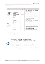
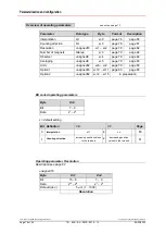
6.4.3 Resolution
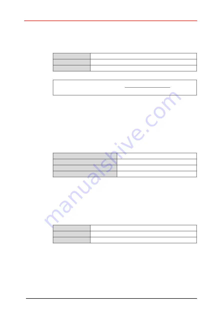
The measuring range stored in the measuring system and the programmed resolution
are used to define the
Total number of steps
across the entire measuring range. The
input is carried out in 0.001 mm steps.
Lower limit
1 µm
Upper limit
1000 µm
Default
5 µm
Measuring length in steps =
Measuring length [mm]
resolution [mm]
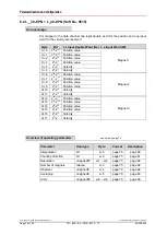
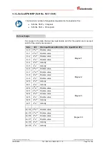
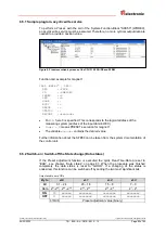
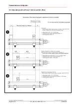
6.4.4 Number of magnets
With this parameter the number of magnets is specified, with which the measuring
system is to be operated. If the input does not agree with the operated number of
magnets, the Data status is set to
BAD
, see also chapter “Data status” on page 87.
Additionally a manufacturer-specific diagnostic alarm (
configuration error
) is
sent by the measuring system to the
controller, also see chapter “PROFINET
” on page 89. The data status changes automatically to
GOOD
, if the
configuration is error free.
Lower limit
1 magnet
Upper limit, Soft. No. 5619, 5637
3 magnets
Upper limit, Soft. No. 5641
30 magnets
Default
1 magnet
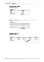
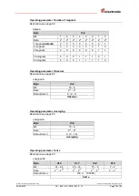
6.4.5 Observer
The Observer performs a mathematical processing of the measured values of the
velocity. In the case of a high measuring dynamics the measured value has no
mathematical post-processing, which results in greater measured value noise, while in
the case of a lower measuring dynamics the measured value noise is considerably
reduced, but this also results in delays in the measured value calculation.
Lower limit
0
Upper limit
7
Default
0
● Dynamic level 0: no mathematical processing
● Dynamic level 1: high measuring dynamics
● …
● Dynamic level 4: middle measuring dynamics
● …
● Dynamic level 7: low measuring dynamics


