Control of the safety-oriented function inputs
TR-Electronic GmbH 2022, All Rights Reserved
Printed in the Federal Republic of Germany
Page 26 of 35
TR-EMO-BA-GB-0023 v00
04/20/2022
6 Control of the safety-oriented function inputs
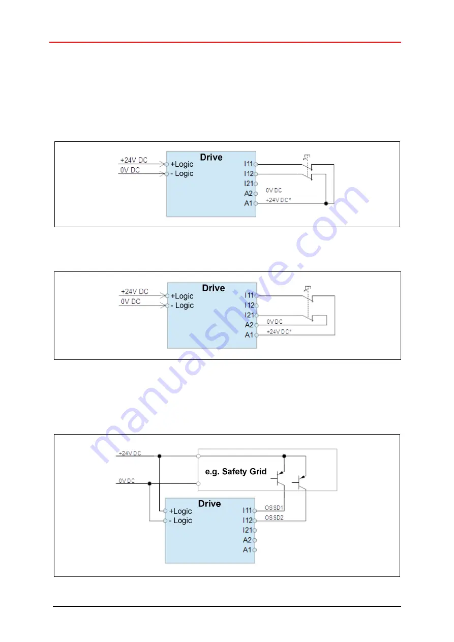
Depending on the application, different options are available for control of the integrated safety mod-
ule, which are implemented by means of specific wiring of inputs I11, I12 and I21. The examples listed
below correspond to the “not safe” state, i.e. the drive is not switched torque-free.
Example 1: Two-channel emergency stop control without cross-circuit monitoring (I11, I12)
Example 2: Two-channel emergency stop control with cross-circuit monitoring (I11, I21)
Example 3: Two-channel semiconductor control without cross-circuit monitoring (I11, I12)
The following diagram shows the wiring of the encoTRive with integrated safety module when con-
nected to electro-sensitive protective equipment (e.g. safety light grid) or similar devices. It is assumed
that the 2-channel input is in non-safe state, if both channels are connected to the supply voltage.


