background image


User's Manual  l  MBa8Xx UM 0100  l  © 2020, TQ-Systems GmbH 


Page  49 


5.2


Notes of treatment 

The TQMa8Xx is held in the mating connectors with a retention force of approximately 28 N. 
To avoid damaging the TQMa8Xx connectors as well as the carrier board connectors while removing the TQMa8Xx  

the use of the extraction tool MOZI8XX is strongly recommended. 
 

Note: Component placement on carrier board 


2.5 mm should be kept free on the carrier board, on both long sides of the MBa8Xx  
for the extraction tool MOZI8XX. 


5.3


Embedding in the target system 

The MBa8Xx serves as a design base for customer products, as well as a reference platform during development. 


5.4


Housing 

The form factor and the mounting holes of the MBa8Xx are designed for installation in a standard EURO housing. 


5.5


Thermal management 

The greatest power dissipation on the MBa8Xx is caused by the voltage regulators. In addition, the TQMa8Xx is a heat source that 

acts indirectly on the MBa8Xx. Depending on the application, further power dissipation can occur, mainly at additional external 

loads on the pin headers on the MBa8Xx, the Mini PCIe slot, etc. 
For evaluation of the TQMa8Xx under high load conditions an optional heat sink or heat spreader is provided. Three holes are 

provided on the MBa8Xx for this purpose. The metallization of the mounting hole has GND potential. 
 

Summary of Contents for MBa8Xx

Page 1: ...MBa8Xx User s Manual MBa8Xx UM 0100 21 12 2020...

Page 2: ...devices 12 3 3 1 Default I2 C interface 12 3 3 2 M4 I2 C interface 14 3 3 3 Further I2 C devices 14 3 4 GPIO port expander 15 3 5 Temperature sensor and EEPROM 16 3 6 RTC backup 17 3 7 USB hub 18 3 8...

Page 3: ...53 6 SAFETY REQUIREMENTS AND PROTECTIVE REGULATIONS 55 6 1 EMC 55 6 2 ESD 55 6 3 Operational safety and personal security 55 7 CLIMATIC AND OPERATIONAL CONDITIONS 55 7 1 Protection against external e...

Page 4: ...24 Table 26 Standard configuration of Ethernet transceivers boot straps 25 Table 27 Ethernet LEDs 25 Table 28 Characteristics Ethernet 1 2 X18 X19 25 Table 29 GPIO TQMa8Xx 26 Table 30 Supply voltage...

Page 5: ...am Dual Channel LVDS 29 Figure 15 Block diagram MIPI CSI 31 Figure 16 Block diagram Mini PCIe 33 Figure 17 Block diagram USB Hub 36 Figure 18 Block diagram USB OTG 37 Figure 19 Block diagram SD card 3...

Page 6: ...and and trademarks are rightly protected by a third party 1 3 Disclaimer TQ Systems GmbH does not guarantee that the information in this User s Manual is up to date correct complete or of good quality...

Page 7: ...used This symbol represents important details or aspects for working with TQ products Command A font with fixed width is used to denote commands file names or menu items 1 7 Handling and ESD tips Gen...

Page 8: ...facturer s specifications of the components used for example CompactFlash cards are to be taken note of They contain if applicable additional information that must be taken note of for safe and reliab...

Page 9: ...MX 8X derivatives are supported 1 i MX 8DualX Dual Cortex A35 2 i MX 8DualXPlus Dual Cortex A35 3 i MX 8QuadXPlus Quad Cortex A35 Note i MX 8DualX reduced functionality The information in this docume...

Page 10: ...ll USB 2 0 Hi Speed Host X22 X24 20 pin DF19G Mini PCIe socket USB 2 0 Hi Speed OTG X29 USB Micro AB USB 3 0 SS Host X20 USB stacked Type A USB debug X13 USB Micro AB The MBa8Xx provides the following...

Page 11: ...levant pins of the CPU are routed to the TQMa8Xx connectors This enables the user to use the TQMa8Xx with all the freedom that comes with a customer specific design in solution Further information can...

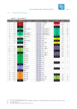
Page 12: ...e suitable mating connectors for the carrier board Table 5 Carrier board mating connectors Manufacturer Pin count part number Remark Stack height X TE connectivity 120 pin 5177986 5 40 pin 5177986 1 O...

Page 13: ...59 60 GND Ground 0 V I 1 8 V 1 ENET ENET0_RXD0 2 61 62 ENET0_TXD0 2 ENET 1 8 V 1 O I 1 8 V 1 ENET ENET0_RXD1 2 63 64 ENET0_TXD1 2 ENET 1 8 V 1 O I 1 8 V 1 ENET ENET0_RXD2 2 65 66 ENET0_TXD2 2 ENET 1...

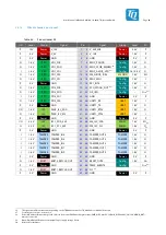
Page 14: ...1 8 V DSI LVDS MIPI_DSI1_D0 61 62 MIPI_DSI0_D0 DSI LVDS 1 8 V O O 1 8 V DSI LVDS MIPI_DSI1_D0 63 64 MIPI_DSI0_D0 DSI LVDS 1 8 V O 0 V Ground GND 65 66 GND Ground 0 V O 1 8 V DSI LVDS MIPI_DSI1_D1 67...

Page 15: ...9 20 CAN1_RX CAN 1 8 V 7 I O 1 8 V 7 TAMPER TAMPER_OUT1 21 22 CAN1_TX CAN 1 8 V 7 O O 1 8 V 7 TAMPER TAMPER_OUT2 23 24 GND Ground 0 V O 1 8 V 7 TAMPER TAMPER_OUT3 25 26 ADC_IN0 ADC 1 8 V I O 1 8 V 7 T...

Page 16: ...de configuration Boot Mode S1 1 BM3 S1 2 BM2 S1 3 BM1 S1 4 BM0 Remark Pos Level Pos Level Pos Level Pos Level Boot from eFuses OFF 0 OFF 0 OFF 0 OFF 0 Serial Downloader USB OTG1 OFF 0 OFF 0 OFF 0 ON 1...

Page 17: ...to the I2C2 This assembly option is described in the MBa8Xx schematics TQMa8Xx I2C1_SCL I2C1_SDA I2C2_SCL I2C2_SDA R266 R267 Level Shifter R371 R372 R373 R374 SN65DSI86 SCL SDA 4 7 k 4 7 k V_3V3_MB He...

Page 18: ...ccess in Protected Mode PCF85063 RTC 0x51 101 0001b MBa8Xx TUSB8041 USB hub optional 0x44 100 0100b Optional TLV320 Audio Codec 0x18 001 1000b SN65DSI86 DisplayPort bridge 0x2C 010 1100b 9FGV0241 PCIE...

Page 19: ...connected to the I2C2 bus As shown in the following table the configuration of the used I C bus is determined by the resistors R371 to R374 Table 11 Assembly option I2C1 I2C2 bus for I C devices on MB...

Page 20: ...m GPIO expander Table 12 Port expander functions Port Signal Dir Remark IO_0 NC I Not connected reserved IO_1 LED_A OPD User LED see chapter 3 9 5 Status LEDs IO_2 LED_B OPD User LED see chapter 3 9 5...

Page 21: ...ted and is not available on the MBa8Xx TQMa8Xx I2C1 SE97BTP I2C Level Shifter Figure 5 Block diagram temperature sensor The I C addresses of the temperature sensor and the EEPROM are determined by the...

Page 22: ...1 k resistor and diode is connected in series between X6 X7 and the LICELL input of the TQMa8Xx The diode has a very low forward voltage 0 1 V in order not to unnecessarily reduce the battery runtime...

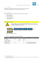
Page 23: ...3 and 4 are externally accessible as USB 3 0 hosts see also chapter 3 8 10 Table 17 shows the power management configured on the MBa8Xx with pull up or pull down resistors Alternatively all settings c...

Page 24: ...e does not require VBUS voltage The USB hub can be configured via the I2C1 bus optional see Table 19 By default the Global Power Reset of the USB hub is connected to the RESET_OUT signal of the TQMa8X...

Page 25: ...m Jack X8 3 5 mm Jack X10 3 5 mm Jack X9 Mic Line Out Line In Figure 8 Block diagram Audio Figure 9 Pinout 3 5 mm jack Table 20 Pinout Audio X8 X9 X10 Channel Pin Signal Dir Level Remark MIC X8 1 AGND...

Page 26: ...Depends on configured common mode voltage Load Line Out Stereo Headphone Stereo Headphone Mono 0 6 k 14 4 24 4 10 k 16 32 Single ended Differential Output power headphone Normal mode Maximum mode 15 m...

Page 27: ...Transceiver TJA1052i Figure 10 Block diagram CAN Table 23 CAN termination DIP switch Interface ON OFF SW1 1 SW1 2 CAN0 CAN0 terminated with 120 CAN0 not terminated SW2 1 SW2 2 CAN1 CAN1 terminated wit...

Page 28: ...ich are converted to USB with the 4 port bridge FT4232 Available UART interfaces UART1 for the Cortex A35 Core SCU_UART for the SCU 2 UART at pin header X4 freely usable e g for additional multiplexed...

Page 29: ...25 MHz 25 MHz Figure 12 Block diagram Ethernet Both transceivers are each connected with their own reset and interrupt signals for which four GPIO signals of the TQMa8Xx are used The following table...

Page 30: ...II Mode disabled The activity status of the respective Ethernet port is indicated by the LEDs in the RJ45 sockets The table shows the default configuration This can be adapted via register settings in...

Page 31: ...ector Output Mux LCD_PWM0 GPIO1_IO29 LCD_RESET Output 10 k Pull Down GPIO1_IO30 LCD_BLT_EN Output 10 k Pull Down GPIO1_IO25 LCD_PWR_EN Output 10 k Pull Down GPIO1_IO13 SWITCH_A User button Input 10 k...

Page 32: ...SI1 I2C1 DisplayPort X23 SN65DSI86 Channel A I2C Channel B ML 3 0 AUX HPD Optional at LVDS Header X14 V_3V3_MB Header X5 IRQ PCA9538A IO_4 EN DP_IRQ Figure 13 Block diagram DisplayPort eDP Note Specif...

Page 33: ...rotection 12 kV Contact Discharge according to IEC 61000 4 2 all signals Table 30 Supply voltage V_3V3_MB at eDP DisplayPort X23 Parameter Min Typ Max Output voltage 3 25 V 3 3 V 3 35 V Output current...

Page 34: ...2 V 5 V as well as USB and configuration signals are available TUSB8041 TQMa8Xx MIPI_DSI0 MIPI_DSI1 USB_OTG2 LVDS Header X14 Optional at DisplayPort Header X23 V_3V3_LVDS LVDS Header X22 V_5V_LVDS V_1...

Page 35: ...rface 1 Lane 3 11 MIPI_DSI0_DATA3 O 1 8 V 12 MIPI_DSI1_DATA0 O 1 8 V DSI interface 2 Lane 0 13 MIPI_DSI1_DATA0 O 1 8 V 14 GND P 0 V Ground 15 MIPI_DSI1_DATA1 O 1 8 V DSI interface 2 Lane 1 16 MIPI_DSI...

Page 36: ...TQMa8Xx GPIO1_IO29 17 LCD_BLT_EN OPD 1 8 V Backlight Enable TQMa8Xx GPIO1_IO30 18 LCD_PWR_EN OPD 1 8 V Power Enable TQMa8Xx GPIO1_IO25 19 LCD_CONTRAST O 1 8 V PWM Contrast Brightness TQMa8Xx GPIO1_IO0...

Page 37: ...served 31 GND P 0 V Ground 32 GND P 0 V 33 MIPI_CSI_D0 I 1 8 V CSI interface Lane 0 34 NC Not connected reserved 35 MIPI_CSI_D0 I 1 8 V CSI interface Lane 0 36 NC Not connected reserved 37 GND P 0 V G...

Page 38: ...et and Interrupt signals of Ethernet Transceiver Voltage MBa8Xx signal TQMa8Xx signal TQMa8Xx pin Remark V_1V5_MPCIE V_1V5_MPCIE_EN GPIO0_IO30 X1 24 High active pulled down to GND V_3V3_MPCIE V_3V3_MP...

Page 39: ...GND P 0 V Ground 22 PCIE_PERST O 3 3 V Power Good of Mini PCIe card 23 PCIE_RX I 0 7 V PCIe receive 24 V_3V3_MPCIE P 3 3 V 3 3 V supply voltage 25 PCIE_RX I 0 7 V PCIe receive 26 GND P 0 V Ground 27 G...

Page 40: ...compulsory to be implemented This prevents the two clock generators from the TQMa8Xx4 and the MBa8Xx driving against each other The separate clock generator 9FGV0241 offers the possibility to vary th...

Page 41: ...5 Gbps This is divided among the connected ports of the USB 3 0 hub Depending on the software and hardware used the effective read and write rates of the ports can vary TQMa8Xx Mini PCIe Slot X24 USB...

Page 42: ...D card standard 3 0 This allows transfer rates of up to 104 Mbyte s The SD card is permanently supplied with 3 3 V the pull ups are also connected to this voltage Signals SW1_WP and SD1_CD have a fixe...

Page 43: ...and X5 if V_1V8 supplied by TQMa8Xx 1 A Sum of currents at X4 and X5 if V_1V8 supplied by regulator on MBa8Xx 22 Note Observe power consumption with regard to the overall system The supply voltages 1...

Page 44: ...D Debug 3 3 V OPD OPU 1 8 V I2C I2C2_SCL 27 28 FTDI_CRXD Debug 3 3 V I I OPU 1 8 V I2C I2C2_SDA 29 30 GND Power 0 V P P 0 V Power GND 31 32 FTDI_DTXD Debug 3 3 V OPD O 1 8 V SPI SPI3_SCK 33 34 FTDI_DR...

Page 45: ...UART1_CTS UART 1 8 V I P 0 V Power GND 33 34 GND Power 0 V P I O 3 3 V I2C I2C1_SDA_3V3 35 36 M4_I2C_SDA M4 I2C 1 8 V I OPU O 3 3 V I2C I2C1_SCL_3V3 37 38 M4_I2C_SCL M4 I2C 1 8 V OPU P 0 V Power GND 3...

Page 46: ...V Watchdog output of i MX 8 4 GND P 0 V Ground 5 JTAG_TDI IPU 1 8 V Test Data In 6 GND P 0 V Ground 7 JTAG_TMS IPU 1 8 V Test Mode Select 8 GND P 0 V Ground 9 JTAG_TCK IPD 1 8 V Test Clock 10 GND P 0...

Page 47: ...Indicates the presence of VBUS for USB Host 3 V5 Green Indicates the presence of VBUS for USB Host 4 V88 Green Indicates the presence of VBUS for USB OTG Mini PCIe V7 Green Shows the status of the WW...

Page 48: ...ely fused Technically an overload of the fuse is therefore possible The resulting total current consumption of the MBa8Xx should be kept below 4 A in total 2 pin terminal X27 DC jack X26 Overcurrent F...

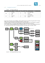
Page 49: ...ges are switched on after the TQMa8Xx boots A 1 8 V supply is already provided by the TQMa8Xx and delivers up to 1000 mA The 1 8 V supply is provided by default directly from the TQMa8Xx via pin X2 12...

Page 50: ...TQMa8Xx TQMa8Xx V_1V8_OUT Level Shifter LM25119 V_5V LM25119 V_1V8 PFET V_3V3_MB VCC_MB_EN optional GPIO0_IO30 GPIO0_IO31 V_1V5_MPCIE_EN LT3503 V_1V5_MPCIE V_3V3_MPCIE_EN FDC6331 V_3V3_MPCIE PCA9538A...

Page 51: ...1V8_OUT controls the regulators for V_5V and V_1V8 as well as the power FET for V_3V3_MB Thus the linear regulators for V_2V5_ETH V_1V0_ETH V_1V2_DP and V_1V1_USB as well as the DC DC regulator for V_...

Page 52: ...ingly in the respective chapters when applicable TQMa8Xx RESET_OUT IMX_ONOFF PMIC_PWRON V_1V8 10 k Level Shifter TUSB8041 GRST 10 k PCA9538A IO_5 NP V_1V8 TLV320 RESET PCA9538A RESET Header X5 Power b...

Page 53: ...nd in the TQ Support Wiki for the TQMa8Xx 5 MECHANICS 5 1 MBa8Xx dimensions The MBa8Xx has overall dimensions length width height of 170 170 27 1 mm The MBa8Xx has six 4 2 mm mounting holes for the ho...

Page 54: ...ign base for customer products as well as a reference platform during development 5 4 Housing The form factor and the mounting holes of the MBa8Xx are designed for installation in a standard EURO hous...

Page 55: ...unting position depending on the specific mode of operation e g dependence on clock frequency stack height airflow and software Attention Tolerance chain Particularly the tolerance chain PCB thickness...

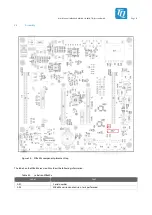
Page 56: ...tems GmbH Page 51 5 6 Assembly Figure 28 MBa8Xx component placement top The labels on the MBa8Xx revision 02xx show the following information Table 54 Labels on MBa8Xx Label Text AK1 Serial number AK2...

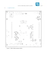
Page 57: ...User s Manual l MBa8Xx UM 0100 l 2020 TQ Systems GmbH Page 52 5 6 Assembly continued Figure 29 MBa8Xx component placement bottom...

Page 58: ...V4 X4 S5 V5 X5 S6 X6 V7 X10 X7 X11 V12 X12 V13 X13 V14 V15 X15 V16 V17 X17 V20 V18 V8 X20 X18 X8 V19 V21 X19 V22 X23 X26 X27 V9 X28 X9 X29 SD Card Audio Status LEDs CAN Ethernet USB 3 0 Host USB 2 0 O...

Page 59: ...User s Manual l MBa8Xx UM 0100 l 2020 TQ Systems GmbH Page 54 5 7 Position of interfaces continued SIM Card X14 X22 X24 J1 X25 Bumper 1 1 Mini PCIe Dual Channel LVDS Figure 31 MBa8Xx interfaces bottom...

Page 60: ...40 C to 100 C Without Lithium battery Relative humidity operation storing 10 to 90 Not condensing Attention TQMa8Xx heat dissipation The i MX 8X CPU belongs to a performance category in which a cooli...

Page 61: ...ly only mounted in sockets 8 6 2 Lithium batteries The requirements concerning special provision 188 of the ADR section 3 3 are complied with for Lithium batteries There is therefore no classification...

Page 62: ...lly Erasable Programmable Read Only Memory EMC Electromagnetic Compatibility EMI Electromagnetic Interference eMMC embedded Multimedia Card Flash EN Europ ische Norm European Standard ESD Electrostati...

Page 63: ...tion of Chemicals RGMII Reduced Gigabit Media Independent Interface RJ 45 Registered Jack 45 RoHS Restriction of the use of certain Hazardous Substances RTC Real Time Clock SAI Serial Audio Interface...

Page 64: ...XP 2 i MX 8DualXPlus i MX 8QuadXPlus Applications Processors Data Sheet 15 May 2020 NXP 3 i MX 8DualXPlus i MX 8QuadXPlus Applications Processor Reference Manual 14 May 2020 NXP 4 i MX 8X Mask Set Err...

Page 65: ...TQ Systems GmbH M hlstra e 2 l Gut Delling l 82229 Seefeld Info TQ Group TQ Group...

Reviews: