background image


User's Manual  l  MBa8x UM 0100  l  © 2021, TQ-Systems GmbH 


Page  11 


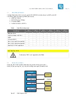
The MBa8x provides the following diagnostic and user interfaces: 


Table 3: 

Diagnostic and user interfaces 

Interface 

Component 

Remark 

Status LEDs 

9 × Green LED 

Power LEDs (24 V, 12 V, 5 V-Mainboard, 5 V-Modul, 3,3 V, 3,3 
V-Mainboard, 3,3 V-Modul, 1,8 V, 3,3 V-MPCIe, 1,5 V-MPCIe) 

3 × Green LED 

2 × VBUS USB Host, 1 × VBUS USB OTG 

1 × Green LED 

Debug LED for USB debug interface 

2 × Green LED 

GP LEDs at port expander 

1 x Orange LED 

GP LED of SCU 

3 × Green LED 

WWAN, WLAN, WPAN 

1 x Green LED 

SATA-M.2 

2 x Green LED 

PCIe-M.2 

1 × Red LED 

Reset LED 

2 × Green / Yellow LED 

Ethernet LEDs (Activity / Speed) 

Temperature sensor 

1 × SE97BTP 

Digital I

2

C temperature sensor 

Power / Reset buttons 

3 × Push button 

RESET-IN#, PMIC_PWRON, IMX_ONOFF 

GP buttons 

2 × Push button 

GP push buttons at port expander 

Boot-Mode configuration 

1 × 6-fold DIP switch 

Boot-Mode configuration 

CAN-FD/RS485 termination 

2 × 2-fold DIP switch 

– 

JTAG 

1 × 20-pin, 100 mil header 

– 


Summary of Contents for MBa8x

Page 1: ...MBa8x User s Manual MBa8x UM Rev 0100 29 11 2021 ...

Page 2: ...urpose push buttons 20 3 8 Battery 21 3 9 LEDs 21 3 10 I2 C devices 22 3 11 GPIO port expander 23 3 12 Temperature sensor 24 3 13 Further devices 24 3 14 Interfaces 24 3 14 1 Audio 24 3 14 2 SPDIF 25 3 14 3 CAN FD 25 3 14 4 MLB 25 3 14 5 USB debug 26 3 14 6 Ethernet 26 3 14 7 GPIO 27 3 14 8 Display interfaces 28 3 14 8 1 DisplayPort 28 3 14 8 2 HDMI In 29 3 14 8 3 LVDS 29 3 14 8 4 MIPI DSI 29 3 14...

Page 3: ... safety and personal security 46 7 CLIMATIC AND OPERATIONAL CONDITIONS 46 7 1 Protection against external effects 46 7 2 Reliability and service life 46 8 ENVIRONMENT PROTECTION 47 8 1 RoHS 47 8 2 WEEE 47 8 3 REACH 47 8 4 EuP 47 8 5 Packaging 47 8 6 Batteries 47 8 7 General notes 47 8 8 Lithium batteries 47 8 9 Other entries 47 9 APPENDIX 48 9 1 Acronyms and definitions 48 9 2 References 50 ...

Page 4: ...Audio 24 Table 13 CAN termination 25 Table 14 Pinout X21 25 Table 15 Ethernet Reset and Interrupt signals 26 Table 16 Characteristics Ethernet 0 X39 27 Table 17 Characteristics Ethernet 1 X40 27 Table 18 GPIO signals 28 Table 19 TQ MIPI DSI adapter 30 Table 20 TQ MIPI CSI adapter 31 Table 21 Power Distribution TUSB8041 34 Table 22 Properties USB host 1 and 2 34 Table 23 Properties of USB OTG 35 Ta...

Page 5: ...net 26 Figure 14 Block diagram LVDS 29 Figure 15 Block diagram MIPI DSI 30 Figure 16 Block diagram MIPI CSI TQ Camera Interface 31 Figure 17 Block diagram Mini PCIe 32 Figure 18 Block diagram PCIe M 2 32 Figure 19 Clock supply PCIe 33 Figure 20 Block diagram SIM card 33 Figure 21 Block diagram USB hub structure of the MBa8x 34 Figure 22 Block diagram USB OTG 35 Figure 23 Block diagram SD card 35 F...

Page 6: ...User s Manual l MBa8x UM 0100 l 2021 TQ Systems GmbH Page v REVISION HISTORY Rev Date Name Pos Modification 0100 29 11 2021 Kreuzer First edition ...

Page 7: ...brand and trademarks are rightly protected by a third party 1 3 Disclaimer TQ Systems GmbH does not guarantee that the information in this User s Manual is up to date correct complete or of good quality Nor does TQ Systems GmbH assume guarantee for further usage of the information Liability claims against TQ Systems GmbH referring to material or non material related damages caused due to usage or ...

Page 8: ...l used This symbol represents important details or aspects for working with TQ products Command A font with fixed width is used to denote commands file names or menu items 1 7 Handling and ESD tips General handling of your TQ products The TQ product may only be used and serviced by certified personnel who have taken note of the information the safety regulations in this document and all related ru...

Page 9: ...anufacturer s specifications of the components used for example CompactFlash cards are to be taken note of They contain if applicable additional information that must be taken note of for safe and reliable operation These documents are stored at TQ Systems GmbH Chip errata It is the user s responsibility to make sure all errata published by the manufacturer of each component are taken note of The ...

Page 10: ...SB SS3 ENET 1 0 OTG1 SAI1 MLB USDHC1 M41 UART PCIE0 LVDS1 x2 MIPI CSI 1 0 MIPI DSI0 JTAG SCU UART Lane 1 2x M 2 Key B Mini PCIe Pin header 0 8 mm OTG2 USB 2 0 Typ Micro GPIO on pin strip HDMI socket DisplayPort socket SD Card Push Pull JTAG pin header TQ camara adapter 60 pin TQ display adapter 60 pin 2x DF19 HF connector 2x 2x Ethernet RJ45 2x mikroBUS socket two 1x8 socket strips USB Micro Pin h...

Page 11: ...LVDS1 CMD X4 20 pin DF19G MIPI CSI X57 60 pin Board to Board header mPCIe X45 Mini PCIe slot USB included X46 SIM card slot Power In X13 DC jack 2 5 mm 5 5 mm X14 2 pin screw terminal block SD card UHS Modes up to 52 MHz X42 Micro SD Push Pull type USB 2 0 Hi Speed Host X4 X7 X45 X47 2 20 pin DF19G mPCIe PCIe M 2 USB 2 0 Hi Speed OTG X29 USB Micro AB USB 3 0 SS Host X36 2 x USB stacked Type A max ...

Page 12: ...een LED Debug LED for USB debug interface 2 Green LED GP LEDs at port expander 1 x Orange LED GP LED of SCU 3 Green LED WWAN WLAN WPAN 1 x Green LED SATA M 2 2 x Green LED PCIe M 2 1 Red LED Reset LED 2 Green Yellow LED Ethernet LEDs Activity Speed Temperature sensor 1 SE97BTP Digital I2 C temperature sensor Power Reset buttons 3 Push button RESET IN PMIC_PWRON IMX_ONOFF GP buttons 2 Push button G...

Page 13: ...the CPU are routed to the TQMa8x connectors This enables the user to use the TQMa8x with all the freedom that comes with a customer specific design in solution Further information can be found in the TQMa8x User s Manual On the MBa8x the standard interfaces like USB Ethernet etc provided by the TQMa8x are routed to industry standard connectors All other signals and buses provided by the TQMa8x are...

Page 14: ...erent height can be used Suitable types can be found on the manufacturer s website To avoid damaging the connectors of the MBa8x or the TQMa8x while removing the TQMa8x the use of the extraction tool MOZIA8X is strongly recommended Note Component placement on carrier board 2 5 mm should be kept free on the carrier board on both long sides of the MBa8x for the extraction tool MOZIA8X 3 4 TQMa8x pin...

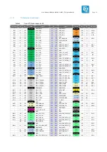
Page 15: ... QSPI QSPI1A_DATA 0 A25 B25 CAN1_TX CAN 1 8 V O G7 Ground GND A26 B26 CAN0_RX CAN 1 8 V I C5 D2 O 1 8 V MLB MLB_CLK A27 B27 CAN0_TX CAN 1 8 V O H6 Ground GND A28 B28 GND Ground E1 O 1 8 V MLB MLB_SIG A29 B29 PCIE0_REFCLK100M_P PCIE 1 8 V I O F26 E3 O 1 8 V MLB MLB_DATA A30 B30 PCIE0_REFCLK100M_N PCIE 1 8 V I O E25 Ground GND FIXED A31 B31 GND FIXED Ground A9 O 1 8 V ENET ENET0_MDC A32 B32 USB_HSIC...

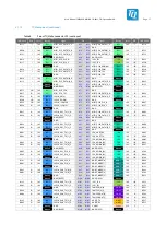
Page 16: ...B42 O 1 8 V ENET ENET0_TXD 1 A81 B81 ENET1_TXD 1 ENET 1 8 V O C47 A45 O 1 8 V ENET ENET0_TXD 2 A82 B82 ENET1_TXD 2 ENET 1 8 V O G47 D42 O 1 8 V ENET ENET0_TXD 3 A83 B83 ENET1_TXD 3 ENET 1 8 V O D48 Ground GND A84 B84 GND Ground B44 I 1 8 V ENET ENET0_RXC A85 B85 ENET1_RXC ENET 1 8 V I B50 Ground GND A86 B86 GND Ground E43 I 1 8 V ENET ENET0_RX_CTL A87 B87 ENET1_RX_CTL ENET 1 8 V I E49 A47 I 1 8 V ...

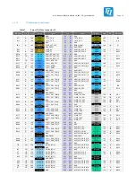
Page 17: ...I 1 8 V O BG1 Ground GND A26 B26 HDMI_TX_DDC_SDA HDMI 1 8 V I O BN5 AT10 I O 1 8 V ESAI ESAI1_TX5_RX0 A27 B27 HDMI_TX_CEC HDMI 1 8 V O BJ1 AY12 I O 1 8 V ESAI ESAI1_TX4_RX1 A28 B28 HDMI_TX_HPD HDMI 1 8 V O BH8 AV10 I O 1 8 V ESAI ESAI1_TX3_RX2 A29 B29 GPIO2_IO 02 GPIO 3 3 V I O BN9 AU11 I O 1 8 V ESAI ESAI1_TX2_RX3 A30 B30 GPIO2_IO 03 GPIO 3 3 V I O BN7 Ground GND FIXED A31 B31 GND FIXED Ground BA...

Page 18: ...SI 1 8 V O BK26 Ground GND FIXED A80 B80 GND FIXED Ground Ground GND A81 B81 GND Ground BG39 O 1 8 V LVDS LVDS0_CH1_TX 2 _N A82 B82 MIPI_DSI0_DATA 0 _N DSI 1 8 V O BM28 BH40 O 1 8 V LVDS LVDS0_CH1_TX 2 _P A83 B83 MIPI_DSI0_DATA 0 _P DSI 1 8 V O BK28 Ground GND A84 B84 GND Ground BG41 O 1 8 V LVDS LVDS0_CH1_TX 1 _N A85 B85 SCU_UART_RX SCU 1 8 V I AU43 BH42 O 1 8 V LVDS LVDS0_CH1_TX 1 _P A86 B86 SCU...

Page 19: ...VDS1_CH1_TX 0 _P A28 B28 ESAI0_TX4_RX1 ESAI 1 8 V I O AV8 Ground GND A29 B29 ESAI0_TX3_RX2 ESAI 1 8 V I O BC5 BK34 O 1 8 V LVDS LVDS1_CH1_CLK_N A30 B30 ESAI0_TX2_RX3 ESAI 1 8 V I O AU9 BM34 O 1 8 V LVDS LVDS1_CH1_CLK_P A31 B31 GND Ground Ground GND A32 B32 ESAI0_TX1 ESAI 1 8 V O BA7 BK36 O 1 8 V LVDS LVDS1_CH0_CLK_N A33 B33 ESAI0_TX0 ESAI 1 8 V O BA9 BM36 O 1 8 V LVDS LVDS1_CH0_CLK_P A34 B34 ESAI0...

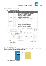
Page 20: ...ode3 SW1 5 Boot Mode4 SW1 6 Boot Mode5 Boot from eFuses 0 0 0 0 0 0 Serial Downloader USB OTG1 0 0 1 0 0 0 eMMC 0 0 0 1 0 0 SD card USDHC1 0 0 1 1 0 0 Flash 3 byte read not supported 0 0 0 1 1 0 Flash 4 byte read not supported 0 1 1 1 1 0 Hyperflash 1 8 V not supported 0 1 0 1 1 0 Note Boot from NAND Booting from NAND is not supported on the MBa8x 3 6 Reset and Power Modes RESET_IN IMX_ONOFF and P...

Page 21: ... I 1 8 V ON OFF function of the i MX 8 low active No pull up on the carrier board required Connect 5 s with GND push button S9 to switch off the CPU Low active pull to GND PMIC_PWRON I 1 8 V Switches PMIC off Off Mode low active No pull up on the carrier board required Low active pull to GND push button S8 Figure 4 Placement push buttons on MBa8X 3 7 General purpose push buttons For simple user in...

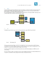
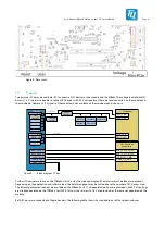
Page 22: ...ry 3 9 LEDs The MBa8x has several LEDs For user outputs two LEDs are available at the signals USER_LED0 and USER_LED1 TQMa8x GPIO 2x 2x User LEDs green Power LEDs green 5 V 3 3 V RESET_OUT RESET LED red Mini PCIE Slot 3x LEDs green Figure 7 Block diagram LEDs LEDs are connected to all main voltages V_24V V_12V V_5V0_MOD V_5V V_3V3 V_1V8 as well as to the MPCIe voltages V_3V3_MPCIE V_1V5_MPCIE In a...

Page 23: ... Clock MIPI_CSI 1 0 _I2C Temperature 1 8 V Level PMIC_I2C I2C2_1V8 I2C1_1V8 I2C1_3V3 HDMI_RX_DDC MIPI_CSI 1 0 HDMI_RX_DDC SE050 MIPI_DSI 1 0 _I2C MIPI_DSI 1 0 HDMI_TX_DDC LVDS 1 0 _CMD LVDS 1 0 _I2C 2k Figure 9 Block diagram I2 C bus Further I2C devices are in use on the TQMa8x which is why the already occupied I2C addresses must be taken into account Depending on the application and software load...

Page 24: ...ith 0 Ω resistors These also allow this connection to be disconnected if required The I2C address depends on the card used and must always be checked to avoid address conflicts I2C1 is connected to the Mini PCIe connector with 0 Ω resistors These also allow this connection to be disconnected if required The I2C address depends on the card used and must always be checked to avoid address conflicts ...

Page 25: ...TP can be found in the data sheet 3 13 Further devices In addition to the port expander and the temperature sensor more devices are connected to the I2C1 These are described in the respective sections for the corresponding interfaces 3 14 Interfaces 3 14 1 Audio The audio codec used is the TLV320AIC3204 from Texas Instruments It is connected to the TQMa8x via SAI configured as I2 S and I2 C The au...

Page 26: ...ted in two transmission modes both of which are supported by the CPU For applications with lower bandwidth the 3 pin implementation single ended is available for applications with high data rates the 6 pin implementation differential The latter allows a data rate of up to 294 912 MHz the 3 pin version offers data rates of up to 49 152 MHz Only one of the interfaces can be used at a time The MLB si...

Page 27: ...nd 1000BASE T The I O voltage of the RGMII signals is 1 8 V Both PHYs are connected with their own PHY reset and interrupt signals Furthermore the interrupt signal of the ENET0 PHY is connected to the module TQMa8x RJ45 ENET0 RGMII0 ENET1 RGMII1 PHY 1 DP83867 PHY 2 DP83867 RJ45 ENET0_SMI ENET1_SMI Figure 13 Block diagram Ethernet Table 15 Ethernet Reset and Interrupt signals Signal TQMa8x signal P...

Page 28: ...n Typ Max Unit Remark Upstream 941 1000 Mbit s Remote station Full Duplex 1 Gbit over CAT 5e Downstream 933 1000 Mbit s 3 14 7 GPIO On the MBa8x some GPIOs are provided by the TQMa8x A distinction is made between general GPIO pins and those that are dedicated to the integrated auxiliary processors SCU ARM M4 CPUs Some GPIOs are provided via a port expander The voltage levels of some pins depend on...

Page 29: ... depending on SD card speed GPIO5_IO20 1 8 V 3 3 V GPIO5_IO23 USDHC1_STROBE IO voltage depending on SD card speed GPIO5_IO23 1 8 V 3 3 V GPIO5_IO 29 24 USDHC2 Interface GPIO5_IO 29 24 1 8 V ESAI1_TX0 GPIO2_IO08 ENET0_INT 1 8 V ESAI1_SCKR GPIO2_IO06 ENET0_RST 1 8 V ESAI1_FSR GPIO2_IO04 ENET1_RST 1 8 V ESAI1_SCKT GPIO2_IO07 USB_RST 1 8 V ESAI1_FST GPIO2_IO05 PCIE_DISABLE 1 8 V ESAI1_TX2_RX3 GPIO2_IO...

Page 30: ...the HDMI socket is connected to GND 3 14 8 3 LVDS The i MX 8 has two LVDS controllers each with a dual LVDS interface or two channels Each of the channels uses four differential lanes for transmission The mainboard allows a single LVDS or dual LVDS to be connected at a time For this reason 2x GPIO BLT_EN RESET one PWR_EN and one PWM signal are provided per LVDS interface The GPIOs are multiplexed ...

Page 31: ...D3 1 8 V GND 19 20 GND 1 8 V MIPI_DSI0_D2 21 22 MIPI_DSI1_D2 1 8 V 1 8 V MIPI_DSI0_D2 23 24 MIPI_DSI1_D2 1 8 V GND 25 26 GND 1 8 V MIPI_DSI0_D1 27 28 MIPI_DSI1_D1 1 8 V 1 8 V MIPI_DSI0_D1 29 30 MIPI_DSI1_D1 1 8 V GND 31 32 GND 1 8 V MIPI_DSI0_D0 33 34 MIPI_DSI1_D0 1 8 V 1 8 V MIPI_DSI0_D0 35 36 MIPI_DSI1_D0 1 8 V GND 37 38 GND 1 8 V MIPI_DSI0_CLK 39 40 MIPI_DSI1_CLK 1 8 V 1 8 V MIPI_DSI0_CLK 41 42...

Page 32: ...MIPI_CSI1_DATA0_N MIPI_CSI0_DATA0_P 35 36 MIPI_CSI1_DATA0_P GND 37 38 GND MIPI_CSI0_CLK_N 39 40 MIPI_CSI1_CLK_N MIPI_CSI0_CLK_P 41 42 MIPI_CSI1_CLK_P GND 43 44 GND MIPI_CSI0_SDA 45 46 MIPI_DSI1_SDA MIPI_CSI0_SCL 47 48 MIPI_DSI1_SCL GND 49 50 GND Master Clock for CSI1 MIPI_CSI0_MCLK_OUT 51 52 MIPI_CSI1_MCLK_OUT Master Clock for CSI1 GND 53 54 GND Reserved for other voltage NC 55 56 V_5V_STBY Always...

Page 33: ... The differential PCIe signals are elongated and have a differential impedance of 85 Ω Furthermore the data lines have the necessary series elements The signals PCIE_PERST PCIE_WAKE and PCIE_CLKREQ are connected to the corresponding connector pins 3 14 12 PCIe Clock Based on previous experience with i MX processors the internal PCIe reference clock does not meet JEDEC jitter specifications NXP the...

Page 34: ... to the reference input of the M 2 slot and is continuously active A placement option to switch off the output is not provided DIF3 is not connected 3 14 13 SATA M 2 An M 2 socket with B coding is used for connecting a SATA SSD In addition mounting options are available for the 2242 and 2280 form factors The differential signals are elongated and have a differential impedance of 85 Ω 10 nF couplin...

Page 35: ...se are generated with the DC DC converter AP7173 FN Power distribution switches are used to supply the USB hosts with 5 V VBUS The following table shows the characteristics of the VBUS supply Table 21 Power Distribution TUSB8041 USB Hub Interface Power Switch Features Max current Current threshold 1 USB Host FPF2165R Thermal Shutdown Reverse Current Protection 900 mA 0 970 A 1 186 A 2 USB Host FPF...

Page 36: ... interface The SDHC controller in the TQMa8x basically supports UHS I SD cards in transfer mode SDR104 according to the SD card standard 3 0 This allows transfer rates of up to 104 Mbyte s The SD card is permanently supplied with 3 3 V the pull ups are also connected to this voltage The signals SW1_WP and SD1_CD have a fixed I O voltage of 1 8 V Their 10 kΩ pull ups are therefore connected to 1 8 ...

Page 37: ...e starter kit pin headers Only modules with 3 3 V IO voltage can be used Therefore two level converters are available for the connection to the 1 8 V logic of the TQMa8x Excluded from the level conversion is the analog signal AN with a maximum input level of 5 V the I2C bus I2C1_3V3 and the reset input The I2C bus can only be operated with 3 3 V level and must be decoupled by removing 0 ohm resist...

Page 38: ... on these headers Besides the signals 1 8 V 3 3 V 5 V and 12 V are available on each header The maximum current load of the individual voltages on the headers depends on the load on other connectors In total no more than the specified maximum current may be drawn at the following interfaces Table 26 Current consumption headers Rail Imax Remark V_12V 2 5 A Sum of currents at X4 X7 X60 X61 X62 X63 X...

Page 39: ...V I O P 0 V Power GND 19 20 GND Power 0 V P I O 1 8 V M4_UART M41_UART_TX 21 22 GPIO4_IO07 GPIO 1 8 V I O O 1 8 V M4_UART M41_UART_RX 23 24 GPIO5_IO23 GPIO VAR I O P 0 V Power GND 25 26 GPIO0_IO05 SIM VAR I O O 1 8 V M4_UART M40_UART_RX 27 28 GND Power 0 V P I O 1 8 V M4_UART M40_UART_TX 29 30 UART1_RX UART0 1 8 V I P 0 V Power GND 31 32 UART1_TX UART0 1 8 V O I 1 8 V UART0 UART0_RX 33 34 UART1_CT...

Page 40: ...1_CS1 SPI1 1 8 V O I O VAR ADC ADC_IN2 17 18 SPI1_SDI SPI1 1 8 V I P 0 V Power GND 19 20 SPI1_SDO SPI1 1 8 V O I O 1 8 V GPIO GPIO1_IO14 21 22 SPI1_SCK SPI1 1 8 V O I O 1 8 V GPIO GPIO1_IO15 23 24 GND Power 0 V P P 0 V Power GND 25 26 SPI2_CS0 SPI2 1 8 V O I 1 8 V SAI1 SAI1_RXFS 27 28 SPI2_CS1 SPI2 1 8 V O I 1 8 V SAI1 SAI1_RXC 29 30 SPI2_SDI SPI2 1 8 V I P 0 V Power GND 31 32 SPI2_SDO SPI2 1 8 V ...

Page 41: ...of V_3V3 and V_V5_MOD all voltages are switched on after the TQMa8x boots The PMICx_PGOOD signals of the module are linked together on the mainboard by means of AND gate and together enable the other controllers in sequence step B This release automatically activates all linear regulators V_2V5_ETH V_1V0_ETH V_1V1_USB V_3V3_MPCIE and V_1V5_MPCIE as well as the DC DC regulator for V_5V_CAN Attentio...

Page 42: ...re on the TQMa8x must be taken into consideration when connecting the heat sink The TQMa8x is not the highest component Inadequate cooling connections can lead to overheating of the TQMa8x and thus malfunction deterioration or destruction 3 17 Fan The CPU s power consumption requires a heat sink and fan for temperature management The fan is controlled directly by the CPU A four pin header X24 with...

Page 43: ... More information can be found in the TQ Support Wiki for the TQMa8x 5 MECHANICS 5 1 MBa8x dimensions The MBa8x has overall dimensions length width of 170 230 mm2 The MBa8x has a maximum height of approximately 26 4 mm The MBa8x has six 4 2 mm mounting holes for the housing and four 2 7 mm mounting holes for a heat sink The MBa8x weighs approximately 294 g without TQMa8x Figure 29 MBa8x dimensions...

Page 44: ... MBa8x plus TQMa8x have a maximum peak power consumption of approx 206 W Further power loss occurs mainly at externally connected devices Attention TQMa8x heat dissipation The i MX 8 CPU belongs to a performance category in which a cooling system is essential It is the user s sole responsibility to define a suitable heat sink weight and mounting position depending on the specific mode of operation...

Page 45: ...User s Manual l MBa8x UM 0100 l 2021 TQ Systems GmbH Page 44 5 5 Assembly Figure 30 MBa8x component placement top ...

Page 46: ...mbH Page 45 5 5 Assembly continued Figure 31 MBa8x component placement bottom The labels on the MBa8x revision 02xx show the following information Table 31 Labels on MBa8x Label Content AK1 Serial number AK2 MBa8x version and revision tests performed ...

Page 47: ...vely cooled Storage temperature 40 C to 70 C With CR2032 battery Attention TQMa8x heat dissipation The i MX 8 CPU belongs to a performance category in which a cooling system could be essential It is the user s sole responsibility to define a suitable heat sink weight and mounting position depending on the specific mode of operation e g dependence on clock frequency stack height airflow and softwar...

Page 48: ...ed with for Lithium batteries There is therefore no classification as dangerous goods Basic lithium content per cell not more than 1 grams except for lithium ion and lithium polymer cells for which a lithium content of not more than 1 5 grams per cell applies equals 5 Ah Basic lithium content per battery not more than 2 grams except for lithium ion batteries for which a lithium content of not more...

Page 49: ...cally Erasable Programmable Read Only Memory EMC Electromagnetic Compatibility EMI Electromagnetic Interference eMMC embedded Multimedia Card Flash EN Europäische Norm European Standard ESD Electrostatic Discharge EuP Energy using Products FR 4 Flame Retardant 4 GP General Purpose GPIO General Purpose Input Output I C Inter Integrated Circuit I S Inter IC Sound IEEE Institute of Electrical and Ele...

Page 50: ...pendent Interface RJ 45 Registered Jack 45 RoHS Restriction of the use of certain Hazardous Substances RTC Real Time Clock SAI Serial Audio Interface SCU System Control Unit SD Secure Digital SDHC Secure Digital High Capacity SDRAM Synchronous Dynamic Random Access Memory SIM Subscriber Identification Module SPI Serial Peripheral Interface SS Super Speed SVHC Substances of Very High Concern TBD To...

Page 51: ...NXP 3 i MX 8DualXPlus 8QuadXPlus Applications Processor Reference Manual 14 May 2020 NXP 4 Mask Set Errata i MX 8 01 May 2020 NXP 5 i MX8 MEK Platform MCIMX8QM CPU EVK SPF 29420_C2 pdf Rev C 17 09 2018 NXP 6 i MX8 QM i MX8 QXP Hardware Developers Guide IMX8_Hardware_Developers_Guide_v2 4p pdf Rev 2 4 06 2021 NXP 7 i MX 8QuadMax Applications Processor Reference Manual Datei iMX8QM_RM_Rev_F pdf Rev ...

Page 52: ...TQ Systems GmbH Mühlstraße 2 l Gut Delling l 82229 Seefeld Info TQ Group TQ Group ...

Reviews: