User's Manual l MBa8MPxL UM 0100 l © 2022, TQ-Systems GmbH
Page 11
3.1.7
Reset
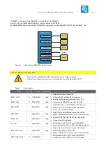
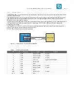
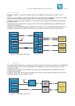
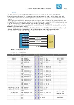
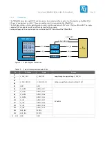
The RESET_OUT# signal of the TQMa8MPxL is available on the MBa8MPxL.
A red LED (V59) on the MBa8MPxL indicates a reset condition; see Table 26.
On the MBa8MPxL a partial reset of the TQMa8MPxL is possible, e.g. with signals PMIC_WDOG_IN# and RESET_IN#.
TQMa8MPxL
RESET_IN#
Button
IMX_ONOFF
RESET_OUT#
System
PMIC_RST#
Button
Button
M7_NMI
PMIC_WDOG#
Header
Figure 6:
Block diagram MBa8MPxL Reset structure
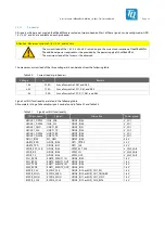
Attention: RESET_OUT# / PMIC_RST#
Attention: The signal RESET_OUT# is designed as a reset triggering signal.
To feed a reset signal into the system, it is mandatory to use the signal PMIC_RST#.
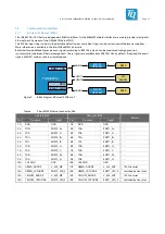
Table 7:
Reset signals
Signal
Dir.
Source
Default
Remark
RESET_OUT#
O
TQMa8MPxL
High
•
Open drain output; low-active
•
Activates RESET of MBa8MPxL components
•
Requires pull-up on carrier board (max. 6.5 V)
RESET_3V3#
O
MBa8MPxL
High
•
Generated on MBa8MPxL from RESET_OUT#
IMX_ONOFF
I
MBa8MPxL
High
•
ON/OFF function; see i.MX 8M Plus data sheet (1)
•
No pull-up on carrier board required; low-active
•
Connect 5 s to GND to activate
PMIC_RST#
I
MBa8MPxL
High
•
No pull-up on carrier board required; low-active
•
Programmable PMIC response (warm reset, cold reset)
RESET_IN#
I
MBa8MPxL
High
•
Activates POR_B of the i.MX 8M Plus; low-active
•
Connect to GND to activate
M7_NMI
I
MBa8MPxL
High
•
Multiplexed to GPIO1_IO05 pin of i.MX 8M Plus
•
Interrupt signal for M7 Sub-CPU with defined priority
PMIC_WDOG_IN#
I
MBa8MPxL
High
•
No pull-up on carrier board required; low-active
•
Disabled by default on PMIC side
•
Programmable PMIC response (warm reset, cold reset)
PMIC_WDOG_OUT#
O
TQMa8MPxL
–
•
Multiplexed to GPIO1_IO02 pin of i.MX 8M Plus
•
Connected to PMIC_WDOG_IN# via 0 Ω bridge


