© 2021 TP-Link
7106509264 RE
V3.1.2
JetStream Gigabit Smart PoE+ Switch
1.
To access the management page of the switch, open a browser and type
the switch’s IP address in the address field, then press the
Enter
key.
If the switch obtains IP address from the DHCP server (typically a router), find
the switch’s IP address on the DHCP server.
If not, use the default IP address
192.168.0.1
to launch the switch’s
management page.
Note: Make sure the switch and computer are in the same subnet.
2.
Enter
admin
for both the username and password in the lower case letters
to log in. The first time you log in, change the password to better protect
your network and devices.
3.
After a successful login, the main page will appear. You can click the menus
on the top side and left side to configure the corresponding functions.
Note:
1. PoE ports can also connect to non-PoE devices, but only transmit data.
2. Maximum PoE power is 30 W for each PoE port, and 62 W (for TL-SG2008P)/61 W (for TL-SG2210P) for all PoE ports.
3. PoE budget calculations are based on laboratory testing. Actual PoE power budget is not guaranteed and will vary as a result of client limitations and environmental factors.
Installation Guide
Configuration
Connection
LED Explanation
On:
Power on
Off:
Power off
Power
Flashing:
System running normally
On/Off:
System running abnormally
System
For TL-SG2008P
On:
55 W ≤ Total power supply < 62 W
Flashing:
Total power supply keeps ≥ 55 W more than
2 minutes
Off:
Total power supply < 55 W
For TL-SG2210P
On:
54 W ≤ Total power supply < 61 W
Flashing:
Total power supply keeps ≥ 54 W more than
2 minutes
Off:
Total power supply < 54 W
PoE MAX
PoE Status
For Port 1-4 of TL-SG2008P/Port 1-8 of TL-SG2210P
On:
Providing PoE power
Flashing:
Current-overload/Short-circuit/Connected
to a non-standard PD/Power exceeded the
user-defined value
Off:
Not providing PoE Power
Link/Act (port 1–8)
On (Green):
Running at 1000 Mbps
On (Yellow):
Running at 10/100 Mbps
Flashing:
Transmitting/receiving data
Off
: No connected device
For the detailed configurations, refer to the User Guide and CLI Guide. The
guides can be found on the download center of our official website:
https://www.tp-link.com/support/download/
.
Method 1: Standalone Mode
Switch
PC
In Standalone Mode, use a computer to configure and manage the switch.
The switch supports two configuration methods:
Standalone Mode: Configure and manage the switch singly.
Controller Mode: Configure and manage the network devices centrally. It is recommended in the large-scale network, which consists of mass devices such as
access points, switches, and gateways.
Note
: When the switch is changed from Standalone Mode to Controller Mode, configurations of the switch will be lost. For details, refer to the related documents on the download center of our
official website: https://www.tp-link.com/support/download/
.
SPF1/SFP2
(for TL-SG2210P)
On (Green):
Running at 1000 Mbps
On (Yellow):
Running at 100 Mbps
Flashing
: Transmitting/receiving data
Off
: No connected device
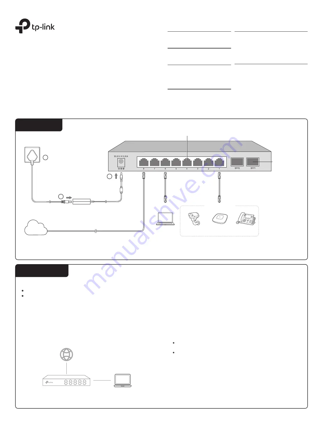
For simplicity, we will take TL-SG2210P for example throughout the Guide.
Ethernet Ports (1–8)
PC
SFP Slots
IP Camera
AP
IP Phone
PoE Devices
DC Power Adapter
AC Power Cord
Internet
1
2
3


