background image

Managing System

Configuring User Account

User Guide  

  13

Configuring User Account

With user account management, you can modify the administrator’s username and 

password in order to refuse illegal users.
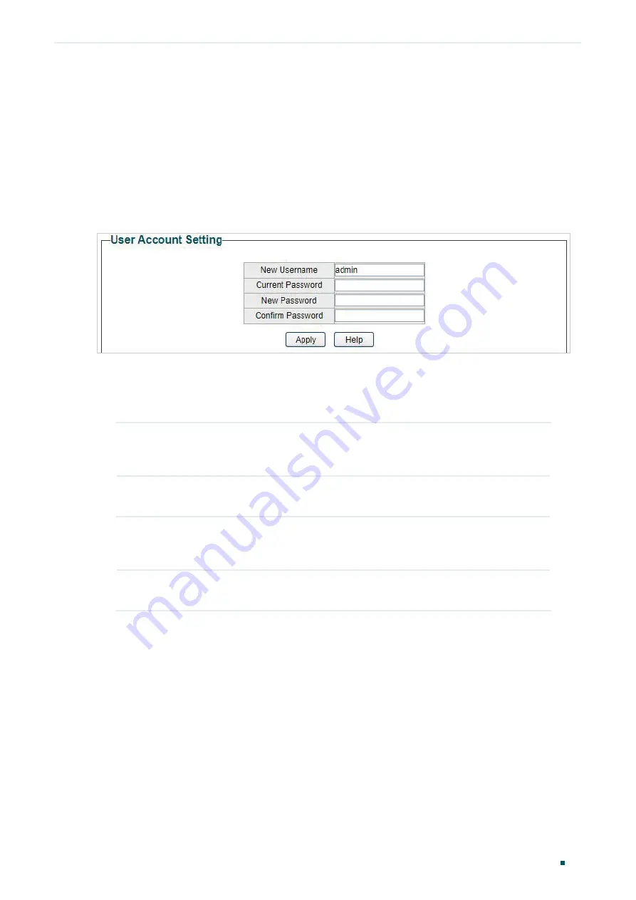
Choose the menu 

System > User Account 

to load the following page.

Figure 5-1 

Configuring User Account

Follow these steps to configure the user account:
1)  Specify the new username, enter the current password, specify a new password and 

confirm the new password.

New Username

Create a user name for login. Requirement for the user name varies among 

different devices. If your user name fails to meet the requirement, check 

the prompt information.

Current 

Password

Enter the current password of the switch. By default, the password is 

admin

New Password

Specify a new password for login. Requirement for the password varies 

among different devices. If your password fails to meet the requirement, 

check the prompt information.

Confirm 

Password

Retype the new password.

2)  Click 

Apply

.

Summary of Contents for Easy Smart Switch

Page 1: ...User Guide Easy Smart Switch 1910012769 REV5 1 0 May 2020...

Page 2: ...the Device Description 9 Configuring IP 10 Configuring LED Only for Certain Devices 12 Configuring User Account 13 Backing up and Restoring the Switch 14 Saving the Current Configuration 14 Restoring...

Page 3: ...res 36 Viewing Port Statistics 37 Configuring Port Mirror 39 Testing Cables 41 Configuring Loop Prevention 43 Appendix Default Parameters 44 Configuring VLAN Overview 46 Configuring MTU VLAN 48 Config...

Page 4: ...e 64 Configuring Bandwidth Control 65 Configuring Storm Control 67 Configuration Example for Basic QoS 69 Network Requirements 69 Configuration Scheme 69 Configuration Steps 70 Appendix Default Parame...

Page 5: ...ll take TL SG1016PE as the switch to be configured for example Some models featured in this guide may be unavailable in your country or region For local sales information visithttps www tp link com Th...

Page 6: ...de the package of the switch The authentication information can be found where you find this guide Specifications can be found on the product page athttps www tp link com To ask questions find answers...

Page 7: ...Part 1 Introduction CHAPTERS 1 Product Overview 2 Logging Into the Switch...

Page 8: ...QoS 802 1P based QoS and DSCP 802 1P based QoS optimize traffic on your business network and keep latency sensitive traffic moving smoothly Bandwidth control helps distribute and utilize network band...

Page 9: ...of 255 255 255 0 3 Configure IP address on your PC to make sure the switch and PC are in the same subnet If the switch uses an IP address assigned by a DHCP server set your PC to obtain an IP address...

Page 10: ...me and password in lower case letters Figure 2 2 Logging Into the Switch Note The first time you log in change the password to better protect your network and devices 7 The typical web interface displ...

Page 11: ...iguring System Info 3 Configuring IP 4 Configuring LED Only for Certain Devices 5 Configuring User Account 6 Backing up and Restoring the Switch 7 Rebooting the Switch 8 Resetting the Switch 9 Upgradi...

Page 12: ...gement User Account Management is mainly used to modify the administrator s username and password in order to refuse illegal users Backup and Restore Backup and Restore is used to download the current...

Page 13: ...ing the System Information Choose the menu System System Info to load the following page You can view the basic system information of the switch Figure 2 1 Viewing the System Summary 2 2 Specifying th...

Page 14: ...nfigure the system IP address using DHCP 1 Select DHCP setting as Enable from the drop down list 2 Click Apply The switch will obtain IP settings from the DHCP server Configuring the System IP Address...

Page 15: ...Managing System Configuring IP User Guide 11 Subnet Mask Specify the subnet mask of the switch Default Gateway Specify the default gateway of the switch 3 Click Apply...

Page 16: ...ation is only available on certain devices To check whether your device supports this feature refer to the actual web interface With this function you can turn on or turn off the LED with one click Ch...

Page 17: ...the current password specify a new password and confirm the new password New Username Create a user name for login Requirement for the user name varies among different devices If your user name fails...

Page 18: ...to the previous configuration 6 1 Saving the Current Configuration Choose the menu System System Tools Backup and Restore to load the following page In the Config Backup section click Backup Config t...

Page 19: ...Backup and Restore to load the following page Figure 6 2 Restoring the Configuration Follow these steps to restore the switch to the previous configuration 1 In the Config Restore section click Choose...

Page 20: ...he switch to the previous configuration It will take effect after the switch automatically reboots Figure 6 4 Restoring to the Previous Configuration Note It will take several minutes to restore the c...

Page 21: ...System System Tools System Reboot to load the following page Click Reboot Figure 7 1 Rebooting the Switch Note It will take several minutes to reboot the switch Wait without any operation while the s...

Page 22: ...Click Reset and the following page will pop up Figure 8 2 Being Sure to Reset the Switch 2 Click OK to reset the switch Note After the switch is reset it will reboot automatically It will take several...

Page 23: ...System Tools Firmware Upgrade to load the following page Figure 9 1 Being Ready to Upgrade the Firmware Follow these steps to upgrade the firmware 1 Click Choose File to load the following page Speci...

Page 24: ...re 9 3 Upgrading the Firmware Note It will take several minutes to upgrade the firmware Wait without any operation Select the proper software version matching with the hardware to upgrade To avoid dam...

Page 25: ...n The model name of the switch Default settings of IP Setting are listed in the following table Table 10 2 Default Settings of IP Address Configuration Parameter Default Setting DHCP Setting Enable IP...

Page 26: ...Part 3 Switching CHAPTERS 1 Switching 2 Configuring Ports 3 Configuring IGMP Snooping 4 Configuring LAG 5 Configuration Examples 6 Appendix Default Parameters...

Page 27: ...dwidth With broadcast information will be sent to all users in the network no matter they need it or not wasting network resources and impacting information security Multicast however solves all the p...

Page 28: ...cast router Layer 2 switch Host A Host B Host C Receiver Receiver Multicast packets transmission with IGMP Snooping Source Multicast router Layer 2 switch Host A Host B Host C Receiver Receiver Multic...

Page 29: ...and set basic parameters for the ports Status Enable or disable the port With this option enabled the port forwards packets normally Otherwise the port cannot work By default it is enabled Speed Duple...

Page 30: ...o notify the peer device to stop sending data for a specific period of time thus avoiding the packet loss caused by congestion 2 Click Apply Note It is recommended to set the ports on both ends of a l...

Page 31: ...age Suppression globally When enabled the switch will only forward the first IGMP report message for each multicast group to the IGMP querier during one query interval and suppress subsequent IGMP rep...

Page 32: ...e steps to configure LAG 1 Select the desired LAG group from the drop down list 2 Click the ports to add to the LAG group Click Apply 3 In the table below you can verify the LAG configuration result Y...

Page 33: ...the aggregation link use the same number of physical ports with the same speed and duplex mode flow control setting and QoS setting Mirroring and mirrored ports cannot be added to an LAG group The max...

Page 34: ...roup As shown in the following topology Host B Host C and Host D are connected to port 1 port 2 and port 3 respectively Port 4 is the router port connected to the multicast querier Figure 5 1 Network...

Page 35: ...1 3 Configuration Steps 1 Choose the menu VLAN 802 1Q VLAN to load the following page Select the 802 1Q VLAN Configuration as Enable Click Apply Specify the VLAN ID as 2 Specify the VLAN name as VLAN2...

Page 36: ...he following page Enable IGMP snooping Click Apply Figure 5 4 Configuring IGMP Snooping 5 2 Example for Configuring LAG 5 2 1 Network Requirements As shown below hosts and servers are connected to Swi...

Page 37: ...Port 2 Port 2 Demonstrated with TL SG1016PE the following section provides configuration steps The configuration steps are similar for both switches here we take Switch A for example 5 2 2 Configurati...

Page 38: ...ting Status Enabled Speed Duplex Auto Flow Control Off Default settings of IGMP Snooping are listed in the following table Table 6 2 Default Settings of IGMP Snooping Configuration Parameter Default S...

Page 39: ...Part 4 Monitoring CHAPTERS 1 Monitoring 2 Viewing Port Statistics 3 Configuring Port Mirror 4 Testing Cables 5 Configuring Loop Prevention 6 Appendix Default Parameters...

Page 40: ...orts mirrored ports to a specified port mirroring port Generally the mirroring port is connected to a data diagnosis device which is used to analyze the mirrored packets for monitoring and troubleshoo...

Page 41: ...resh the data Port Displays the port number of the switch Status Displays whether the port is enabled or disabled Link Status Displays the link state of the port TxGoodPkt Displays the number of packe...

Page 42: ...bytes less than 64 bytes or with bad FCS Frame Check Sequence are recorded as BadPkts Because of the supporting feature of jumbo frame the frames with more than 1518 bytes and less than 10000 bytes wi...

Page 43: ...the menu Monitoring Port Mirror to load the following page Figure 3 1 Configuring Port Mirror Follow these steps to configure port mirror 1 Enable the port mirror feature globally Specify a mirroring...

Page 44: ...each port select whether the ingress packets are mirrored With this option enabled the packets received by the port will be copied to the mirroring port With this option disabled the packets received...

Page 45: ...e selected ports 2 Check the test results in the table Port Displays the port number Test Result Displays the connection status of cables Test results include Normal Close or Short Open and Crosstalk...

Page 46: ...ting Cables Cable Fault Distance m If the connection status is Normal here displays the length of the cable If the connection status is Close or Short Open or Crosstalk here displays the length from t...

Page 47: ...n Choose the menu Monitoring Loop Prevention to load the following page Figure 5 1 Configuring Loop Prevention Follow these steps to configure loop prevention 1 Enable or disable loop prevention Loop...

Page 48: ...re listed in the following table Table 6 1 Default Settings of Port Mirrror Configuration Parameter Default Setting Port Mirror Disable Default settings of Loop Prevention are listed in the following...

Page 49: ...Part 5 Configuring VLAN CHAPTERS 1 Overview 2 Configuring MTU VLAN 3 Configuring Port Based VLAN 4 Configuring 802 1Q VLAN 5 Configuration Example for 802 1Q VLAN 6 Appendix Default Parameters...

Page 50: ...enant Unit VLAN defines an uplink port which will build up several VLANs with each of the other ports Each VLAN contains two ports the uplink port and one of the other ports in the switch so the devic...

Page 51: ...the port as its VID and then forward it as a tagged frame Note The switch works in one and only one VLAN mode at any time When a specific VLAN mode is enabled the other two VLAN modes will be disable...

Page 52: ...configure MTU VLAN 1 Select MTU VLAN configuration as Enable Click Apply MTU VLAN Configuration Enable or disable the MTU VLAN mode 2 In the table below change the uplink port from the drop down list...

Page 53: ...r the VLAN and ports to add to the VLAN Click Apply VLAN ID Select the ID for the VLAN which you want to add ports to Member Select the ports to add to the VLAN 3 In the table below you can verify the...

Page 54: ...N To complete the 802 1Q configuration follow these steps 1 Configure the VLAN including creating a VLAN and adding the ports to the VLAN 2 Configure the PVID 4 1 Configuring the VLAN Choose the menu...

Page 55: ...ber Set the port as an untagged port as a tagged port or not as a member port in the VLAN Untagged Select the egress rule of the port as Untagged An untagged port will forward frames after removing th...

Page 56: ...Figure 4 2 Configuring 802 1Q PVID Follow these steps to configure the PVID 1 Select the ports and set the PVID for the ports PVID Set the PVID for the ports The PVID ranges from 1 to 4094 2 Click App...

Page 57: ...th departments can access the internet Hosts of the same department can communicate with each other but hosts of different departments cannot Figure 5 1 Network Topology VLAN 2 Department A VLAN 3 Dep...

Page 58: ...Table 5 1 Relationships of Ports and VLANs on Switch A and Switch B Switch Ports in VLAN 1 Ports in VLAN 2 Ports in VLAN 3 Switch A 2 3 4 2 4 3 4 Switch B 1 2 3 4 1 2 4 1 3 4 Table 5 2 Settings of Eg...

Page 59: ...with TL SG1016PE the following section provides configuration steps The configuration steps on both switches are similar Here we take Switch A for example 1 Choose the menu VLAN 802 1Q VLAN to load th...

Page 60: ...LAN 2 Choose the menu VLAN 802 1Q VLAN to load the following page and create VLAN 2 Specify VLAN ID as 2 add port 2 to the VLAN as an untagged port and add port 4 to the VLAN as a tagged port Click Ad...

Page 61: ...pecify VLAN ID as 3 add port 3 to the VLAN as an untagged port and add port 4 to the VLAN as a tagged port Click Add Modify Figure 5 4 Creating VLAN 3 and Adding Ports to the VLAN 4 Choose the menu VL...

Page 62: ...User Guide 58 Configuring VLAN Configuration Example for 802 1Q VLAN Figure 5 5 Configuring 802 1Q PVID...

Page 63: ...Default Setting MTU VLAN Configuration Disable Table 6 2 Default Settings of Port Based VLAN Configuration Parameter Default Setting Port Based VLAN Configuration Enable VLAN ID 1 VLAN Member Port 1 5...

Page 64: ...Part 6 Configuring QoS CHAPTERS 1 QoS 2 Configuring Basic QoS 3 Configuring Bandwidth Control 4 Configuring Storm Control 5 Configuration Example for Basic QoS 6 Appendix Default Parameters...

Page 65: ...th the QoS feature You can configure QoS Basic Bandwidth Control and Storm Control on the switch to maximize the network performance and bandwidth utilization QoS Basic The switch classifies the ingre...

Page 66: ...PRI value Lowest 0 1 Normal 2 3 Medium 4 5 Highest 6 7 In this mode the switch only prioritizes packets with VLAN tag regardless of the IP header of the packets DSCP 802 1P Based DSCP priority determ...

Page 67: ...e as Port Based Click Apply QoS Mode Select the QoS mode Port Based In port based mode the switch prioritizes packets according to their ingress ports regardless of the packet field or type 2 In the P...

Page 68: ...ckets 2 Click Apply 2 3 Configuring QoS in DSCP 802 1P Based Mode Choose the menu QoS QoS Basic to load the following page Figure 2 3 Configuring Basic QoS in DSCP 802 1P Based Mode Follow these steps...

Page 69: ...Select the desired ports and configure the ingress rate and egress rate for the ports Ingress Rate Kbps Configure the bandwidth for receiving packets on the port If the rate for receiving packets on...

Page 70: ...e time If you enable ingress rate control for a port storm control will be disabled for that port automatically When egress rate is set for one or more ports it is recommended to disable the flow cont...

Page 71: ...orm control 1 Select the desired ports and configure the upper rate limit for forwarding broadcast packets multicast packets and UL frames Unknown unicast frames Status Enable or disable the storm con...

Page 72: ...on the port they will be discarded Multicast If multicast packets traffic exceeds the rate on the port they will be discarded Broadcast If broadcast packets traffic exceeds the rate on the port they w...

Page 73: ...Figure 5 1 Basic QoS Application Topology RD Dept Marketing Dept Router Port 3 Port 1 Port 2 Switch A Internet 5 2 Configuration Scheme To implement this requirement you can configure QoS in port bas...

Page 74: ...load the following page In the Global Config section select QoS mode as Port Based Click Apply Figure 5 2 Configuring Basic QoS in Port Based Mode 2 In the Port Based Priority Setting section specify...

Page 75: ...Figure 5 3 Setting Different Priorities for Port 1 and Port 2...

Page 76: ...efault settings of Bandwidth Control configuration are listed in the following table Table 6 2 Default Settings of Bandwidth Control Configuration Parameter Default Setting Ingress Rate Kbps Unlimited...

Page 77: ...Part 7 Configuring PoE Only for Certain Devices CHAPTERS 1 Overview 2 Configuring PoE 3 Configuring PoE Auto Recovery 4 Appendix Default Parameters...

Page 78: ...ones access points APs and cameras may be located far away from the AC power source in actual use PoE can provide power for these devices without requiring to deploy power cables This allows a single...

Page 79: ...s to configure PoE 1 In the Global Config section you can view the current PoE parameters You can configure the System Power Limit Click Apply System Power Limit Configure the maximum power the PoE sw...

Page 80: ...e running of other PDs Power Limit 0 1 w 30 w Specify the maximum power the corresponding port can supply The following options are provided Class 1 The maximum power that the port can supply is 4 W C...

Page 81: ...e Follow these steps to enable PoE Auto Recovery and configure the parameters 1 In the Global Config section enable or disable PoE Auto Recovery Click Apply PoE Auto Recovery Enable or disable PoE Aut...

Page 82: ...fails to get the ping response from the PD on the port the switch will retry until the number of ping failures reaches the threshold then the switch reboots the PD Break Time Specify how soon the swi...

Page 83: ...etting Global Config System Power Limit 150 0 W Port Config PoE Status Enabled Startup Delay Low Interval Class 4 Default settings of PoE Auto Recovery are listed in the following table Table 4 2 Defa...

Page 84: ...are trademarks or registered trademarks of their respective holders No part of the specifications may be reproduced in any form or by any means or used to make any derivative such as translation trans...

Reviews: