Typical Network Topology
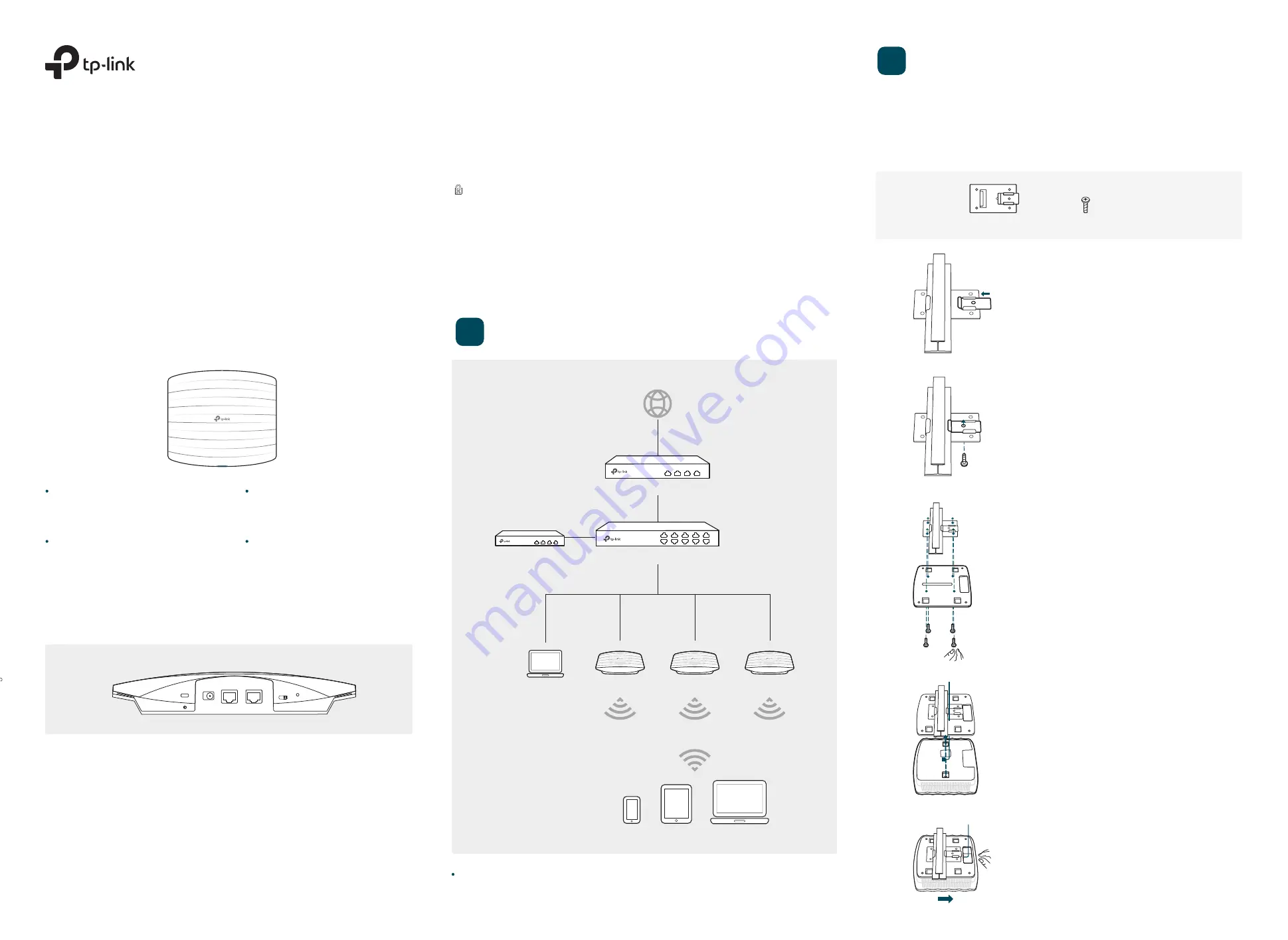
Option 1: Ceiling Rail Mounting
Quick Installation Guide
CAP2200
AC2200 Wireless Tri-Band MU-MIMO Ceiling Mount Access Point
LED Indication
Interface Panel
RESET
With the device powered on, press and hold the button for about 8 seconds until the LED
flashes red, then release the button. The device will restore to factory default settings.
The device is working properly.
Solid green
System errors. RAM, Flash,
Ethernet, WLAN or firmware may
be malfunctioning.
Flashing red
The device is being reset to its
factory default settings.
Double-flashing red, green, yellow
Firmware update is in progress. Do not
disconnect or power off the device.
Flashing yellow
The port is used to connect to a router or a switch to transmit data or to a PSE (Power Sourcing
Equipment), such as a PoE switch, for both data transmission and Power over Ethernet (PoE)
through Ethernet cabling.
ETH1(PoE)
The port is used to connect to a router or a switch to transmit data. ETH2 and ETH1 can be
combined together to double the network backhaul capacity.
ETH2
1
5
Push the CAP along the direction of arrows until
it locks into place, as shown on the left. Then
adjust the cable to make the exposed part
hidden behind the CAP.
2
Use an M3×6 pan-head screw to secure the T-rail
Clip onto the ceiling rail.
1
Position the Ceiling T-rail Clip and push the movable
part toward the rail base.
3
Attach the mounting bracket to the Ceiling T-rail Clip
using four M3x6 pan-head screws.
4
Make the Ethernet Cable pass through the fixing
hole of the mounting bracket. Connect the cable to
the Ethernet port and attach the CAP to the bracket.
Ceiling T-rail Clip
M3×6 Pan-head Screws
(Qty.5)
CAP
CAP
CAP
Management Host
Switch
Router
Internet
Clients
RESET
ETH1(PoE)
ETH2
POWER
FIT FAT
Wireless Controller
The wireless controller can be in the same or different network segment with the CAPs.
Hardware Installation
2
The CAP can be ceiling-mounted or wall-mounted.
Note: Please take the power supply into consideration before the installation.
FIT FAT
The FIT/FAT switch is used to toggle the CAP’s working mode. The toggling of the mode will
reboot the CAP.
In FIT mode, CAPs can be centrally managed by TP-Link’s wireless controller. The default
FIT mode is used when you want to deploy a large wireless network.
In FAT mode, you can log in to CAP’s webpage to manage the AP alone. The FAT mode is
used in a small wireless network. The CAP cannot be managed by wireless controller in FAT
mode.
The kensington lock port is used to connect to a kensington lock to secure your CAPs.
Kensington
POWER
The port is used to connect the CAP to a power socket via the provided power adapter.


