


A93841
A85760
90
_
14
−
24
−
ENGINE MECHANICAL
PARTIAL ENGINE ASSY (1CD
−
FTV)(From September,
2003)
1CD
−
FTV ENGINE REPAIR MANUAL (RM1046E)
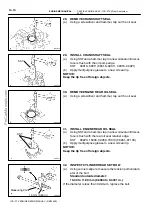
(e)
Install the nozzle holder clamp as shown in the illustration.
Tighten the camshaft bearing cap bolt by hand to fix the
nozzle holder clamp.
NOTICE:
S
Pay attention to the mounting orientation of the wash-
er.
S
When temporarily attaching the nozzle holder clamp
and mounting bolt, be careful not to orient them at an
angle.
HINT:
Apply a light coat of engine oil to the threads of the nozzle hold-
er clamp bolts.
(f)
Install the injection pipe No. 1, No. 2, No. 3 and No. 4, then
tighten the nuts by hand.
(g)
Install new 5 gaskets and the leakage pipe No. 1. Tighten
the 4 hollow screws by hand.
(h)
Tighten the 4 nozzle holder clamp bolts.
Torque: 26 N
×
m (265 kgf
×
cm, 19 ft
×
lbf)
(i)
Remove the 4 injection pipes.
54.
INSTALL NOZZLE LEAKAGE PIPE ASSY
(a)
Remove the bolt which is tightened at the center of the
camshaft bearing cap No. 4.
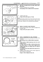
(b)
Install the nozzle leakage pipe and 4 new gaskets.
NOTICE:
When installing the gaskets, pay attention to the mounting
orientation. Install the gasket so that the joint of the gasket
comes within the ranges shown in the illustration.
(c)
Apply a light coat of engine oil to the 4 hollow screws and
bolt.
(d)
Tighten the 4 hollow screws and bolt by hand.
(e)
Tighten the 4 hollow screws and bolt.
Torque:
16 N
×
m (163 kgf
×
cm, 12 ft
×
lbf) for hollow screw
20 N
×
m (204 kgf
×
cm, 15 ft
×
lbf) for flange bolt
NOTICE:
In any case, when the torque exceeds the upper limit, re-
place the leakage pipe hollow screw and gaskets with new
ones.
(f)
Check that there are no leaks from the nozzle leakage
pipe connection.
(1)
Apply a light coat of soapy water (any fluid to detect
fuel leakage) to the nozzle leakage pipe connec-
tion.