


Town Food Service Equipment Company, Inc.
718/388-5650 outside New York State 800/221-5032
mbr-36 mbr-42
3
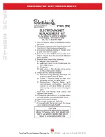
SAFETY PILoT, ouT oNLY
number 249011
3
/
8
” FEMALE GAS VALVE
number 226102F
figure 1
PlaNNING aND SITE PrEParaTIoN, CoNTINuED
6) use of the supplied regulator is mandatory. The regulator must be installed in a location where it remains
cool and is accessible for pressure adjustment (ANSI z83.11-1996 Sect. 1.15.5).
a) If installed in a facility with a high pressure gas system a 1st stage regulator must be supplied by
others. The supply appliance regulator must be installed downstream from the 1st stage regulator.
Never iNstall the appliaNce regulator uNderNeath or iN the ceNter of the uNit
7) Equipment should be under hood with adequate ventilation.
uNCraTING aND PlaCING THE uNIT
CLEARANCES FRoM NoNCoMBuSTIBLE CoNSTRuCTIoN ARE ThE SAME AS CoMBuSTIBLE CLEARANCES.
ThIS APPLIANCE IS SuITABLE FoR INSTALLATIoN oNLY oN NoNCoMBuSTIBLE FLooRS.
1) The top is shipped in a separate crate. Position crate next to the location that the unit will occupy.
uncrate the range, place it in position and take note of the position of gas feed line.
2) Carefully place the range into desired position to avoid damage to adjustable legs. Be sure unit is located with the
clearances away from combustible construction as indicated on the rating plate of the unit. Turn all three gas valve
lever handles to
off
position (figure 1). Check that three valves face in the position desired by customer.
3) Place cast iron top on the support tubes.
cautioN: the custom cast iron top is over 1” thick and is
extremely heavy.
Make sure the
“
ribs
”
on the bottom of the cook top do not sit on the support tubes.
We reccommend using a licensed rigger for installation.
4) Level the unit using the adjustable bullet feet at the end of each leg.
GaS INSTallaTIoN
1) The installation must conform with the National Fuel Gas Code, ANSI Z223.1, Natural Gas Installation Code,
CAN/CGA-B149.1 or the Propane Installation Code, CAN/CGA-B149.2, as applicable, including:
a) The appliance and it
’
s individual shutoff valve must be disconnected from the gas supply piping
system during any pressure testing of that system at test pressures in excess of
1
/
2
psi (3.45 kPa).
b) The appliance must be isolated from the gas supply piping system by closing it
’
s individual manual valve
during any pressure testing of the gas supply piping system at test pressures equal or less than 0.5 PSIG
(3.45 kPa).
2) The installation must conform with all local authority regulations governing gas appliance installations.
CoNTINuED
oN
PaGE
4