tousek
/ EN_ST-12-5_05 / 25. 03. 2020
- 31 -
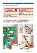
• Now implement the spacers (D) according to the lower diagram, fit the new control board ST12/5 and fix it with screws into
the existing housing
.
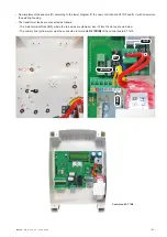
• The transformer leads are connected as follows:
- The 3-pin terminal block
(K1)
, where the red wires are clamped, insert it into the slot as shown below.
- The primary line (yellow wire) must be connected to terminals
5/6 (PRIM)
of the control board ST 12/5.
K1
yellow
PRIM
Control unit ST 12/5
D
red


