Page 77
TMP86PM29BUG
8.3.3
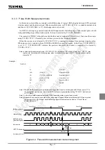
Pulse Width Measurement mode
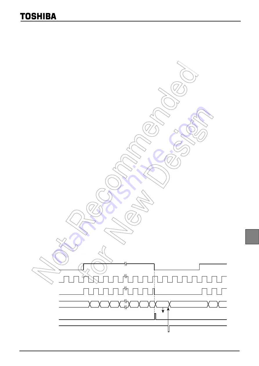
In this mode, pulse widths are counted on the falling edge of logical AND-ed pulse between ECIN pin input
(window pulse) and the internal clock. When using this mode, set TC1CR1<TC1CK> to suitable internal clock
and then set TC1CR2<SEG> to “0” (Both edges can not be used).
An INTTC1 interrupt is generated when the ECIN input detects the falling edge of the window pulse or both
rising and falling edges of the window pulse, that can be selected by TC1CR2<SGEDG>.
The contents of TREG1A should be read while the count is stopped (ECIN pin is low), then clear the counter
using TC1CR1<TC1C> (Normally, execute these process in the interrupt program).
When the counter is not cleared by TC1CR1<TC1C>, counting-up resumes from previous stopping value.
When up counter is counted up from 3FFFFH to 00000H, an overflow occurs. At that time, TC1SR<HEOVF>
is set to “1”. TC1SR<HEOVF> remains the previous data until the counter is required to be cleared by
TC1CR1<TC1C>.
Note:In pulse width measurement mode, if TC1CR1<TC1S> is written to "00" while ECIN input is "1", INTTC1 inter-
rupt occurs. According to the following step, when timer counter is stopped, INTTC1 interrupt latch should be
cleared to "0".
Note 1: When SGEDG (window gate pulse interrupt edge select) is set to both edges and ECIN pin input is "1" in
the pulse width measurement mode, an INTTC1 interrupt is generated by setting TC1S (TC1 start control)
to "10" (start).
Note 2: In the pulse width measurement mode, HECF (operating status monitor) cannot used.
Note 3: Because the up counter is counted on the falling edge of logical AND-ed pulse (between ECIN pin input and
the internal clock), if ECIN input becomes falling edge while internal source clock is "H" level, the up
counter stops plus "1".
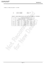
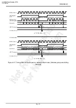
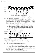
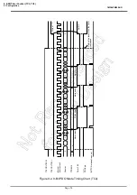
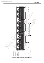
Figure 8-4 Pulse width measurement mode timing chart
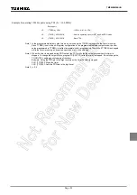
Example :
TC1STOP :
¦
¦
DI
; Clear IMF
CLR
(EIRH). 0
; Clear bit0 of EIRH
LD
(TC1CR1), 00011010B
; Stop timer couter 1
LD
(ILH), 11111110B
; Clear bit0 of ILH
SET
(EIRH). 0
; Set bit0 of EIRH
EI
; Set IMF
¦
¦
1
0
2
3
n-2
n-1
n
n+1
0
1
2
ECIN pin input
INTTC1 interrupt
Internal clock
AND-ed pulse
(Internal signal)
Up counter
TC1CR1<TC1C>
Interrupt
Read Clear
Count Start
Count Start
Count Stop
Summary of Contents for TLCS-870/C Series
Page 1: ...8 Bit Microcontroller TLCS 870 C Series TMP86PM29BUG ...
Page 6: ...TMP86PM29BUG ...
Page 7: ...Revision History Date Revision 2007 10 11 1 First Release 2008 8 29 2 Contents Revised ...
Page 9: ......
Page 15: ...vi ...
Page 19: ...Page 4 1 3 Block Diagram TMP86PM29BUG 1 3 Block Diagram Figure 1 2 Block Diagram ...
Page 23: ...Page 8 1 4 Pin Names and Functions TMP86PM29BUG ...
Page 48: ...Page 33 TMP86PM29BUG ...
Page 49: ...Page 34 2 Operational Description 2 3 Reset Circuit TMP86PM29BUG ...
Page 61: ...Page 46 3 Interrupt Control Circuit 3 8 External Interrupts TMP86PM29BUG ...
Page 81: ...Page 66 6 Watchdog Timer WDT 6 3 Address Trap TMP86PM29BUG ...
Page 135: ...Page 120 10 8 Bit TimerCounter TC5 TC6 10 1 Configuration TMP86PM29BUG ...
Page 145: ...Page 130 11 Asynchronous Serial interface UART 11 9 Status Flag TMP86PM29BUG ...
Page 165: ...Page 150 13 10 bit AD Converter ADC 13 6 Precautions about AD Converter TMP86PM29BUG ...
Page 183: ...Page 168 15 LCD Driver 15 4 Control Method of LCD Driver TMP86PM29BUG ...
Page 201: ...Page 186 18 Electrical Characteristics 18 9 Handling Precaution TMP86PM29BUG ...
Page 203: ...Page 188 19 Package Dimensions TMP86PM29BUG ...
Page 205: ......

