Strata CT Installation
2-44
Strata CT I&M Manual October 2000
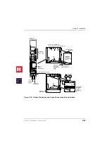
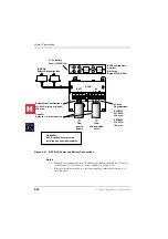
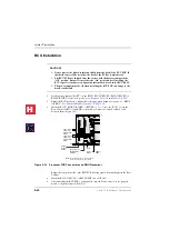
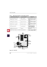
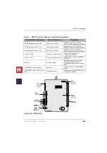
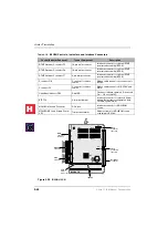
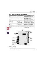
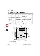
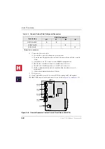
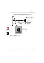
Figure 2-26
B2CBU PCB
Table 2-10
B2CBU Controls, Indicators, and Interface Connectors
Control/Indicator/Connector
Type of Component
Description
DTMF Receiver Connector P5
16-pin male connector
Interface connector for optional DTMF
receiver subassembly (BRCS).
DTMF Receiver Connector P6
10-pin male connector
Interface connector for optional DTMF
receiver subassembly (BRCS).
DTMF Receiver Connector P7
6-pin male connector
Interface connector for optional DTMF
receiver subassembly (BRCS).
Connector P10
Connector for ribbon
cables
Ribbon cable connector for connection to
B2CAU.
Connector P3
Connector for ribbon
cables
Ribbon cable connector for B2CAU and
RSIU.
Heart Beat indicator CD5
Red LED
Flashes to indicate operation (1/4 second
On — 1/4 second Off).
BATT P9
3-terminal jumper
Interface connector for on-board lithium
battery that protects configuration data
stored in system RAM.
MOH/BGM Source Connector
RCA jack
Interface connector for MOH/BGM
source.
MOH/BGM Source Volume Control
VR1
Trim potentiometer
Adjusts volume for MOH/BGM source
connected to B3CAU.
B2CBU1A
5023
BATT
ON
OFF
B2CBU1A
P6
IC11
C5
IC10
IC6
IC9
IC12
P7
P5
P10
P3
P9
P2
P1
CBRUNK
RKYS
Feature
Key Socket
UP
BRCS
Connector
(J1 to P5)
Backplane
Connector
BRCS
Connector
(J4 to P2)
BRCS
Connectors
(J3 to P7)
B2CAU
Connector
RSIU
Connector
H
C
Summary of Contents for Strata CT
Page 36: ...Strata CT Configuration 1 22 Strata CT I M Manual October 2000 H C ...
Page 94: ...Strata CT Installation 2 58 Strata CT I M Manual October 2000 H C ...
Page 242: ...Peripheral Installation 6 54 Strata CT I M Manual October 2000 H C ...
Page 258: ...ACD Installation 7 16 Strata CT I M Manual October 2000 H C ...
Page 274: ...Fault Finding 8 16 Strata CT I M Manual October 2000 H C ...
Page 364: ...ISDN Interfaces 10 38 Strata CT I M Manual October 2000 H C ...
Page 370: ...Notes to Users A 6 Strata CT I M Manual October 2000 H C ...

