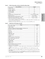
DK40i Configuration
Base Key Service Unit (KSU)
2-4
Strata DK I&M 6/00
Base Key Service Unit (KSU)
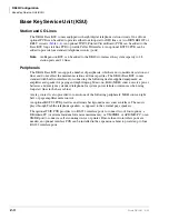
Station and CO Lines
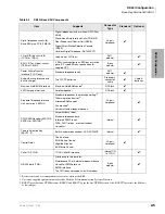
The DK40i Base KSU comes equipped with eight digital telephone station circuits. One of four
optional PCBs can be added to provide either four loop start or DID lines, or two ISDN BRI S/T or
BRI-U circuits (
). An optional TCIU2 Printed Circuit Board (PCB) can be added to the
Base KSU loop start line PCB to provide Caller ID interface. An optional KSTU2 PCB can be
added to provide four standard telephone circuits (ports).
Note
An Expansion KSU can be added to the DK40i to increase the system capacity to 28
station ports and 12 lines.
Peripherals
The DK40i Base KSU can support a number of peripherals, which are not considered as stations or
lines and do not affect the maximum station and line capacities. The DK40i Base KSU comes
standard with built-in interfaces for connecting the following dealer-supplied equipment: an
amplifier and speaker for paging and night ringing, Music-on-Hold (MOH) source, reserve power
batteries, and emergency standard telephone for system power failure occurrences when using
loop start lines in the base cabinet.
A relay contact is also provided to control one of the following peripherals: MOH source, night
bell, or page amplifier mute control.
An optional KSTU2 PCB provides an alternate background music source interface. The music
plays through Toshiba telephone speakers, as opposed to the external page speakers.
The optional TSIU PCB provides two RS-232 interface ports to connect two of four options: a
DKAdmin PC (or external modem for remote maintenance); or VM SMDI; or ACD/MIS PC; or an
SMDR port to connect a call accounting device or printer. If more than two interface ports are
needed, an optional interface PCB can be installed in the expansion cabinet to provide up to four
RS-232 interface ports.
Summary of Contents for Strata AirLink DK40i
Page 22: ...Introduction Related Documents Media xx Strata DK I M 6 00 ...
Page 48: ...DK14 Installation DK14 Wiring Diagrams 1 26 Strata DK I M 6 00 ...
Page 220: ...DK424 Installation Remote Cabinet Installation Instructions 5 68 Strata DK I M 6 00 ...
Page 262: ...DK424i Configuration Primary Reserve Power Cabinet Hardware 6 42 Strata DK I M 6 00 ...
Page 450: ...Universal Slot PCB Wiring Option Interface PCB Wiring Diagrams 10 42 Strata DK I M 6 00 ...
Page 592: ...Peripheral Installation Enhanced 911 Service E911 12 84 Strata DK I M 6 00 ...
Page 616: ...ACD Installation Spectrum Electronic Wall Boards 13 24 Strata DK I M 6 00 ...
Page 634: ...Fault Finding Fault Isolation Flowcharts 14 18 Strata DK I M 6 00 ...
Page 704: ...ISDN Interfaces ISDN Disconnect Cause Code 16 54 Strata DK I M 6 00 ...

