


30
Address Setup
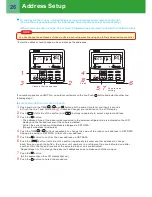
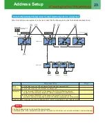
<Clearing Indoor Unit address>
U1 U2
U1 U2
U1 U2
U1 U2
U1 U2
U5 U6
U3 U4
U1 U2
U5 U6
U3 U4
U1 U2
U5 U6
U3 U4
A B
A B
A B
A B
(1)
(2) (4)
(3)
(5)
(6)
Outdoor unit
Indoor unit
Remote
controller
Remote
controller
Remote
controller
Header unit (A)
Follower unit (B)
Follower unit (C)
k
c
e
h
C
s
m
e
ti
k
c
e
h
c
n
i
a
M
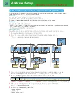
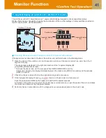
(1) Are the indoor and outdoor communication lines of the header unit connected to the U1/U2 terminals?
(2) Is the relay connector between the U1/U2 terminal and the U3/U4 terminal disconnect? (Set up at
shipment from the factory)
(3) Is the communication line between outdoor units connected to the U5/U6 terminal?
(4) Is the terminator (SW30-bit 2) on the interface PC board of the header unit turned on? (Set up at
shipment from the factory)
(5) Is the terminator of the shield wire open?
(6) Is the terminator of the shield wire earthed at the header unit side?
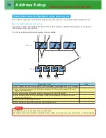
Prior to the test operation, check the following items to verify there are no problems with the installation work.
Main check items for electric wiring
The communication system differs from that of R22 or R407 refrigerant “Modular Multi System” air conditioners.
Check wiring points again carefully.
(1) In the case that a central control system is not connected:
NOTE
The figure above does not show all the electric wires.
For details, refer to the installation manuals for the outdoor unit, indoor unit, remote controller, or optional devices.
Chaeck items before Test Operation ( before powering - on)
Summary of Contents for SMMS-e
Page 96: ...Quick Reference ...