


15
Address Setup
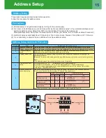
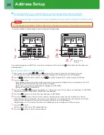
This product requires address setup before operation.
Follow this procedure for address setup.
(1) Address setup is not performed simply by turning on the power supply.
(2) For indoor units, address setup can be done either by “manual address setup” or “by automatic address setup”
Automatic address setup: Setup from SW15 on the interface PC board of the header unit
Manual address setup: Setup from the wired remote controller. (For details, refer to “Address Setup Procedure.”)
(3) Automatic setup usually takes about 5 minutes per line. In some cases, however, it may take up to 10 minutes.
(4) It is unnecessary to operate the air conditioner to achieve address setup.
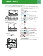
Procedure
1
Indoor unit power-on
Turn on the power of the indoor unit for the refrigerant line for which the address is to be set up.
2
Outdoor unit power-on Turn on the power of all the outdoor units for the refrigerant line for which the address is to be set up .
3
7-segment display
check
Check that “L08” is displayed on the 7-segment display [B] on the interface PC board of the
header unit in the system where the address is to be set up.
4
Address setup start
Confirm the items in “Address Setup Procedure,” and then set up the address according to the
operation procedure.
(Be careful to note that the setup operation may differ in group control and central control systems.)
Note:
The address cannot be set up if switches are not operated.
s
t
n
e
t
n
o
c
k
c
e
h
c
d
n
a
n
o
it
a
r
e
p
O
m
e
tI
5
Display check after
setup
• After address setup, “U1” “ ” is displayed on the 7-segment display.
• For follower outdoor units, “U2” to “U3” are displayed on the 7-segment display [A].
• If an error code is displayed on the 7-segment display [B], remove the cause of the problem
referring to “TROUBLESHOOTING”.
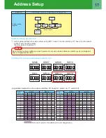
6
System information
check after setup
Using the 7-segment display function, check the system information of the scheduled system.
(This check is executed on the interface PC board of the header unit.)
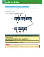
System capacity
[Number of
horsepower]
[Ton]
1
2
3
SW01 SW02 SW03
[A]
[B]
Rotary switch setup
7-segment display
Number of connected
outdoor units
[Number of units]
[ P]
1
3
3
Number of connected
indoor units
[Number of
connected units]
1
4
3
After the above checks, return rotary switches SW01, SW02, and SW03 to 1/1/1.
Interface PC board
SW01 SW02 SW03
SW04
D600 D601 D602 D603 D604
SW15
SW05
Push switches
Rotary switches
7-segment display
[A]
7-segment display
[B]
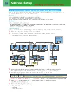
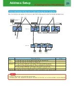
Address Setup
Address Setup and Check Procedure
Precautions
Summary of Contents for SMMS-e
Page 96: ...Quick Reference ...