background image

User’s Manual

6-1

Power and Power-up Modes

Chapter 6

Power and Power-up Modes

The computer’s power resources include the AC adaptor and internal 

batteries. This chapter gives details on making the most effective use of 

these resources including charging and changing batteries, tips for saving 

battery power, and power-up modes.

Power Conditions

The computer’s operating capability and battery charge status are affected 

by the power conditions: whether an AC adaptor is connected, whether a 

battery is installed and what the charge level is for the battery.


Power on

Power off 

(no operation)

AC adaptor 

connected

Battery fully 

charged

• Operates
• 

DC IN/Battery

 LED: 

green

• 

DC IN/Battery

 LED: 

green

Battery partially 

charged or no 

charge

• Operates
• Quick Charge
• 

DC IN/Battery

 LED: 

amber

• Quick charge
• 

DC IN/Battery

 LED: 

amber

No battery 

installed 

• Operates 
• No charge
• 

DC IN/Battery

 LED: 

green

• No charge
• 

DC IN/Battery

 LED: 

green

Summary of Contents for Satellite Pro C640

Page 1: ...computers toshiba europe com User s Manual Satellite C640 C640D Satellite Pro C640 C640D Series ...

Page 2: ...play 1 6 Turning On The Power 1 7 Starting Up for The First Time 1 7 Turning Off The Power 1 8 Restarting The Computer 1 11 System Recovery Options 1 12 System Recovery 1 13 Chapter 2 The Grand Tour Front with The Display Closed 2 1 Left Side 2 1 Right Side 2 2 Back Side 2 3 Underside 2 4 Front with The Display Open 2 5 System Indicators 2 7 Keyboard Indicator 2 8 Optical Disc Drive 2 9 AC Adaptor...

Page 3: ...rity Lock 3 22 Chapter 4 Operating Basics Using The Touchpad 4 1 Using The Web Camera 4 2 Using The TOSHIBA Face Recognition 4 5 Using Optical Disc Drives 4 8 Writing CD DVDs on DVD Super Multi R DL Drive 4 14 TOSHIBA Disc Creator 4 18 TOSHIBA DVD PLAYER 4 20 Media Care 4 23 Sound System 4 23 Using The Microphone 4 26 Wireless Communications 4 27 LAN 4 28 Cleaning The Computer 4 30 Moving The Comp...

Page 4: ...tery Pack 6 10 Starting The Computer by Password 6 12 Power up Modes 6 13 Chapter 7 HW Setup and Passwords Accessing HW Setup 7 1 HW Setup Window 7 1 Chapter 8 Troubleshooting Problem Solving Process 8 1 Hardware and System Checklist 8 3 TOSHIBA Support 8 13 Appendix A Specifications Appendix B Display Controller and Video Mode Appendix C Wireless LAN Appendix D AC Power Cord and Connectors Append...

Page 5: ...curacy The instructions and descriptions it contains are accurate for the TOSHIBA Satellite C640 C640D Satellite Pro C640 C640D Series Portable Personal Computer at the time of this manual s production However succeeding computers and manuals are subject to change without notice TOSHIBA assumes no liability for damages incurred directly or indirectly from errors omissions or discrepancies between ...

Page 6: ...se of another type of battery or AC adaptor may risk fire or explosion Before you connect the computer to a power source ensure that the voltage rating of the AC adaptor matches that of the available power source 115 V 60 Hz in most of North and South America and some Far Eastern countries such as Taiwan 100 V 50 Hz in eastern Japan and 100 V 60 Hz in western Japan 230 V 50 Hz in most of Europe th...

Page 7: ...that this product still observes these EMC standards if options or cables not produced by TOSHIBA are connected or implemented In this case the persons who have connected implemented those options cables have to provide assurance that the system PC plus options cables still fulfils the required standards To avoid general EMC problems the following guidance should be noted Only CE marked options sh...

Page 8: ...tion of products and batteries you will help to assure the proper disposal of products and batteries and thus help to prevent potential negative consequences for the environment and human health For more detailed information about the collection and recycling programmes available in your country please visit our website http eu computers toshiba europe com or contact your local city office or the ...

Page 9: ...s entered into force on 1 June 2007 Toshiba will meet all REACH requirements and is committed to provide our customers with information about the chemical substances in our products according to REACH regulation Please consult the following website http www toshiba europe com computers info reach for information about the presence in our articles of substances included on the candidate list accord...

Page 10: ...h the power management options preset to a configuration that will provide the most stable operating environment and optimum system performance for both AC power and battery modes To conserve energy your computer is set to enter the low power Sleep Mode which shuts down the system and display within 15 minutes of inactivity in AC power mode TOSHIBA recommend that you leave this and other energy sa...

Page 11: ...nic System Networks UJ890AD UJ890ED The drive employs a laser system To ensure proper use of this product please read this manual carefully and retain for future reference Should the unit ever require maintenance contact an authorized service location Use of controls adjustments or the performance of procedures other than those specified may result in hazardous radiation exposure To prevent direct...

Page 12: ...O COMPLY WITH DHHS RULES 21 CFR CHAPTER 1 SUBCHAPTER J APPLICABLE AT THE DATE OF MANUFACTURE MANUFACTURED Toshiba Samsung Storage Technology Korea Corporation 14F Digital Empire II 486 Sin dong Youngtong gu Suwon si Gyeonggi Do Korea 443 734 Location of the required label COMPLIES WITH FDA RADIATION PERFORMANCE STANDARDS 21 CFR SUBCHAPTER J MANUFACTURED Hitachi LG Data Storage Inc 22 23 Kaigan 3 c...

Page 13: ...TED JUNE 24 2007 MANUFACTURED TEAC CORPORATION 1 47 OCHIAI TAMA SHI TOKYO JAPAN CAUTION This appliance contains a laser system and is classified as a CLASS 1 LASER PRODUCT To use this model properly read the instruction manual carefully and keep this manual for your future reference In case of any trouble with this model please contact your nearest AUTHORIZED service station To prevent direct expo...

Page 14: ...devices such as a printer be sure to read Chapter 3 Hardware Utilities and Options This manual is composed of the following chapters appendixes a glossary and an index Chapter 1 Getting Started is an overview of the computer s features capabilities and options Chapter 2 The Grand Tour identifies the components of the computer and briefly explains how they function Chapter 3 Hardware Utilities and ...

Page 15: ... keyboard keys are used in the text to describe many computer operations A distinctive typeface identifies the key top symbols as they appear on the keyboard For example ENTER identifies the ENTER key Key operation Some operations require you to simultaneously use two or more keys We identify such operations by the key top symbols separated by a plus sign For example CTRL C means you must hold dow...

Page 16: ...generated by the computer that appears on its display screen is presented in the type face you see to the left Pay attention A caution informs you that improper use of equipment or failure to follow instructions may cause data loss or damage your equipment Please read A note is a hint or advice that helps you make best use of your equipment Indicates a potentially hazardous situation which could r...

Page 17: ...mputer or AC adaptor with any object Never place your computer or AC adaptor near a heat source such as anelectric blanket or heater Never cover or block the air vents including those located at the base of the computer Always operate your computer on a hard flat surface Using your computer on a carpet or other soft material can block the vents Always provide sufficient space around the computer O...

Page 18: ... touch if you maintain physical contact with the computer for a long time for example if you rest the computer on your lap or if you keep your hands on the palm rest your skin might suffer a low heat injury If the computer has been used for a long time avoid direct contact with the metal plate supporting the various interface ports as this can become hot The surface of the AC adaptor can become ho...

Page 19: ... Pro C640 C640D Series Instruction Manual for Safety and Comfort All important information on the safe and proper use of this computer is described in the enclosed Instruction Manual for Safety and Comfort Be sure to read it before using the computer ...

Page 20: ...ersonal Computer Battery pack AC adaptor and power cord 2 pin plug or 3 pin plug Documentation Satellite C640 Satellite C640D Satellite Pro C640 Satellite Pro C640D Series Quickstart Instruction Manual for Safety and Comfort Limited Warranty If any of the items are missing or damaged contact your dealer immediately Software Windows 7 The following software is preinstalled Some of the features desc...

Page 21: ...ay Turning on the power Starting up for the first time Turning off the power Restarting the computer System recovery options Restoring the pre installed software from the Recovery hard disk drive Restoring the pre installed software from your created Recovery Media If you are a new user follow the steps in each section of this chapter as you prepare to operate your computer All users should be sur...

Page 22: ...o charge the battery pack refer to Chapter 6 Power and Power up Modes Use a virus check program and make sure it is updated regularly Never format storage media without checking its content formatting destroys all stored data It is a good idea to periodically back up the internal hard disk drive or other main storage device to external media General storage media is not durable or stable over long...

Page 23: ...g in serious injury The supplied power cord conforms to safety rules and regulations in the region the product is bought and should not be used outside this region For use in other regions please buy power cords that conform to safety rules and regulations in the particular region Do not use a 3 pin to 2 pin conversion plug When you connect the AC adaptor to the computer always follow the steps in...

Page 24: ...DC output plug to the DC IN 19V jack on the left side of the computer Connecting the adaptor to the computer 3 Plug the power cord into a live wall outlet the DC IN Battery indicator on the front of the computer should glow Either a 2 pin or 3 pin adaptor cord will be included with the computer depending on the model ...

Page 25: ... panel Opening it vigorously or slamming it shut could damage the computer Be careful not to open the display panel too far as this could put stress on the display panel s hinges and cause damage Do not press or push on the display panel Do not lift the computer by the display panel Do not close the display panel with pens or any other objects left in between the display panel and the keyboard Whe...

Page 26: ...g on the power Starting Up for The First Time The Windows 7 Startup Screen will be the first screen displayed when you turn on the power Follow the on screen instructions on each screen in order to properly install the operating system After you turn on the power for the first time do not turn it off until you have set up the operating system Please refer to the section Starting Up for The First T...

Page 27: ...king right where you left off Make sure the Optical Disc Drive indicator is off If you turn off the power while a disk disc is being accessed you may lose data or damage the disk Never turn off the power while an application is running Doing so could cause loss of data Never turn off the power disconnect an external storage device or remove storage media during data read write Doing so can cause d...

Page 28: ... is in Sleep Mode The computer or the memory module could be damaged Do not remove the battery pack while the computer is in Sleep Mode unless the computer is connected to an AC power source Data in memory will be lost When the AC adaptor is connected the computer will go into Sleep Mode according to the settings in the Power Options to access it Start Control Panel System and Security Power Optio...

Page 29: ...turn to your previous working environment immediately when you turn on the computer Saves power by shutting down the system when the computer receives no input or hardware access for the time period set by the System Hibernate feature Allows the use of the panel power off feature Starting Hibernation Mode When the computer is shut down in Sleep Mode the power indicator will blink amber If you are ...

Page 30: ... take a moment to save the current data in memory to the hard disk drive After you turn off the computer and the content of memory has been saved to the hard disk drive turn off the power to any peripheral devices Restarting The Computer Certain conditions require that you reset the computer for example if You change certain computer settings An error occurs and the computer does not respond to yo...

Page 31: ... the system See the Windows Help and Support content for more information about Startup Repair The System Recovery Options can also be run manually to repair problems The procedure is as follows Follow the instructions shown on the on screen menu 1 Turn off the computer 2 While holding the F8 key turn on the computer 3 The Advanced Boot Options menu will be displayed Use the arrow keys to select R...

Page 32: ...le you wish to copy and then click the Create button Be sure to connect the AC adaptor when you create Recovery Media Be sure to close all other software programs except the Recovery Media Creator Do not run software such as screen savers which can put a heavy load on the CPU Operate the computer at full power Do not use power saving features Do not write to the media when the virus check software...

Page 33: ...talled software from your created Recovery Media If the pre installed files are damaged you are able to either use the Recovery Media you have created or the hard disk drive recovery process to restore the computer to the state it was in when you originally received it To perform this restoration follow the steps below When the sound mute feature has been activated by pressing the FN ESC key be su...

Page 34: ... which you should follow the on screen instructions Ordering Recovery Discs from TOSHIBA You can order Product Recovery discs for your notebook from the TOSHIBA Europe Backup Media Online Shop 1 Visit https backupmedia toshiba eu on the Internet 2 Follow the on screen instructions You will receive your Recovery Discs within two weeks after placing your order When you reinstall the Windows operatin...

Page 35: ...ows the computer s front with its display panel in the closed position Front of the computer with display closed Left Side Figure below shows the computer s left side The left side of the computer 1 DC IN 19V 2 Optical disc drive DC IN 19V The AC adaptor connects to this socket Use only the model of AC adaptor that comes with the computer Using the wrong adaptor can damage your computer Optical di...

Page 36: ...mes faster than the USB 1 1 standards Keep foreign objects out of the USB connectors A pin or similar object can damage the computer s circuitry Operation of all functions of all USB devices has not been confirmed Some functions might not execute properly Headphone jack A standard 3 5 mm mini headphone jack enables connection of a stereo headphone 16 ohm minimum or other device for audio output Wh...

Page 37: ...desk or other large object to deter theft Fan vent Provides air flow for the fan Be careful not to block the fan vent Also be careful to keep foreign objects out of the vents A pin or similar object can damage the computer s circuitry External monitor port This 15 pin port allows you to connect an external monitor LAN jack This jack allows you to connect to a LAN The adaptor has built in support f...

Page 38: ...onnected The Batteries section in Chapter 6 Power and Power up Modes describes how to access the battery pack Additional battery packs can be purchased from your TOSHIBA dealer to extend the computer s battery operating time Battery pack lock Slide the battery pack lock to unlocked position to free the battery release latch Battery release latch Slide this latch to release the battery pack This la...

Page 39: ...r right 3 Built in microphone 8 Touchpad 4 Power button 9 System indicators 5 Stereo speaker left 10 Touchpad control buttons Web camera Record Send still or video images with this integrated web camera Provided with some models Web camera LED The web camera LED glows blue when the web camera software is used Provided with some models Built in microphone Records monaural sounds into your applicati...

Page 40: ...er when operating on batteries For more information on the computer s display please refer to the Display Controller and Video Mode section in Appendix B Touchpad Moves the pointer and selects or activates items on the screen Can be set to perform other mouse functions such as scrolling selecting and double clicking Please handle your computer carefully to avoid scratching or damaging the surface ...

Page 41: ...ndicator glows green when the computer is on If you turn off the computer in Sleep Mode this indicator blinks green If the computer shuts down this indicator shows no light DC IN Battery The DC IN Battery indicator shows the condition of the charge Green means fully charged and glows amber means being charged During critical low battery the indicator will blink amber Refer to Chapter 6 Power and P...

Page 42: ...gure below shows the position of the CAPS LOCK indicator When the CAPS LOCK indicator glows the keyboard is in all caps mode CAPS LOCK indicator 1 CAPS lock indicator CAPS LOCK This indicator glows green when letter keys are locked into their uppercase format ...

Page 43: ... the type of discs it can write Use TOSHIBA Disc Creator to write compact discs Refer to Chapter 4 Operating Basics CDs CD R discs can be written only once The recorded data cannot be erased or changed CD RW discs can be recorded more than once DVDs DVD R DVD R DVD R DL and DVD R DL discs can be written only once The recorded data cannot be erased or changed DVD RW DVD RW and DVD RAM discs can be ...

Page 44: ...r 60 hertz enabling you to use the computer in almost any region To recharge the battery simply connect the AC adaptor to a power source and the computer See Chapter 6 Power and Power up Modes for details The AC adaptor 2 pin plug The read speed is slower at the centre of a disc and faster at the outer edge DVD read 8 speed maximum DVD R write 8 speed maximum DVD RW write 6 speed maximum DVD R wri...

Page 45: ... of this region In order to use the adaptor computer in other regions you should please buy a power cord that conforms to the safety rules and regulations in that particular region Always use the TOSHIBA AC adaptor that was included with your computer or use AC adaptors specified by TOSHIBA to avoid any risk of fire or other damage to the computer Use of an incompatible AC adaptor could cause fire...

Page 46: ...our model open the TOSHIBA PC Diagnostic Tool Utility by clicking Start All Programs TOSHIBA Utilities PC Diagnostic Tool Slots PC3 8500 1 GB 2 GB or 4 GB memory modules can be installed in the two memory slots Maximum system memory size and speed are depending on the model you purchased Video RAM 6 Depending on the model you purchased Mobile Intel HM55 Express Chipset model Video RAM capacity sha...

Page 47: ...record data to rewritable CD DVDs as well as run CD DVDs without using an adaptor It reads DVD ROMs at maximum 8 speed and CD ROMs at maximum 24 speed It writes CD R at up to 24 speed CD RW at up to 24 speed DVD R at up to 8 speed DVD RW at up to 6 speed DVD RAM at up to 5 speed DVD R at up to 8 speed DVD RW at up to 8 speed DVD R DL at up to 6 speed and DVD R DL at up to 6 speed This drive suppor...

Page 48: ...wer Features 2 Select On battery from the drop down menu in Graphics Power Plan Settings and then select the Display Power Saving Technology check box If you want to improve the picture quality under the conditions mentioned above adjust the setting towards Maximum Quality or disable this feature Please visit your region s web site or refer to the catalog for the configuration details of the model...

Page 49: ... recharges the batteries when they are low It comes with a detachable power cord Because it is universal it can receive a range of AC voltage between 100 and 240 volts Headphone Enables connection of a stereo headphone Microphone Enables connection of a microphone External monitor 15 pin analog VGA port Universal Serial Bus USB 2 0 ports Two Universal Serial Bus USB enable a chain connection of US...

Page 50: ... Orthogonal Frequency Division Multiplexing radio technology that complies with the IEEE 802 11 Standard Revision B G and N Roaming over multiple channels Security lock slot Connects a security lock to anchor the computer to a desk or other large object Operating system Windows 7 is available Refer to the preinstalled Software section at the Chapter 1 Getting Started TOSHIBA Utilities A number of ...

Page 51: ...em in Sleep Mode or Hibernation Mode when there is no input or hardware access for a time specified This can be specified in the Power Options Keypad overlay A ten key pad is integrated into the keyboard Refer to the Keypad overlay section in Chapter 5 The Keyboard for instructions on using the keypad overlay Power on password Two levels of password security supervisor and user are available to pr...

Page 52: ... long battery life Hibernation This feature allows you to turn off the power without exiting from your software The contents of main memory are saved to the hard disk when you turn on the power again you can continue working right where you left off Refer to the Turning Off The Power section in Chapter 1 Getting Started for details Sleep If you have to interrupt your work you can turn off the powe...

Page 53: ...ther key is pressed TOSHIBA Assist TOSHIBA Assist is a graphical user interface that provides access to specific tools utilities and applications that make the use and configuration of the computer easier HW Setup utility To start the utility click the Windows Start button point to All Programs click TOSHIBA click Utilities and select HWSetup icon TOSHIBA DVD PLAYER This software is provided for p...

Page 54: ...n uses a face verification library to verify the face data of users when they log in to Windows If the verification is successful the user will be logged into Windows automatically The user can thus avoid having to enter a password or the like which makes the login process easier Is preinstalled with some models TOSHIBA HDD SSD Alert The TOSHIBA HDD SSD Alert includes wizard functions to monitor t...

Page 55: ...itive user interface To access this utility click Start All Programs TOSHIBA TOSHIBA ReelTime TOSHIBA Media Controller This application allows you to control your music pictures and videos by streaming content to any compatible device in your home To access this utility click Start All Programs TOSHIBA TOSHIBA Media Controller TOSHIBA Media Controller For more information please refer to the TOSHI...

Page 56: ...emory media with various memory capacities so that you can easily transfer data from devices such as digital cameras and Personal Digital Assistants USB FDD kit The USB floppy disk drive accommodates either a 1 44 MB or 720 KB floppy disk through connection to one of the computer s USB ports In use please be aware that while you cannot format 720 KB floppy disks under Windows 7 you are able to rea...

Page 57: ...r distinguishing SD memory cards from SDHC and SDXC memory cards SD SDHC and SDXC memory cards appear the same externally The logo on SD SDHC and SDXC memory cards are different so pay careful attention to the logo when purchasing This Bridge media slot supports the following memory media Secure Digital SD Card SD memory card SDHC memory card SDXC memory card miniSD Card and microSD Card MultiMedi...

Page 58: ...ot with the format command provided within Windows Media Care Observe the following precautions when handling the card Card Care Do not twist or bend cards Do not expose cards to liquids or store in humid areas or lay media close to containers of liquid Do not touch the metal part of a card or expose it to liquids or let it get dirty After using card return it to its case The card is designed so t...

Page 59: ...le read write is in progress About the Write protect The following memory media have a function for protect SD Card SD memory card SDHC memory card SDXC memory card Inserting a Memory Media The following instructions apply to all types of supported media devices To insert a memory media follow the steps as detailed below 1 Insert the memory card 2 Press gently to ensure a firm connection For more ...

Page 60: ...rchased 1 Bridge media slot 2 The memory card When inserting memory media do not touch the metal contacts You could expose the storage area to static electricity which can destroy data Do not turn the computer off or switch to Sleep Mode or Hibernation Mode while files are being copied doing so may cause data to be lost ...

Page 61: ...p the card and remove it Removing the inserted memory card The card s shape depends on the card you purchased 1 The memory card If you remove the memory media or turn off the power while the computer is accessing the memory media you may lose data or damage the media Do not remove the memory media while the computer is in Sleep Mode or Hibernation Mode The computer could become unstable or data in...

Page 62: ...y Pack section in Chapter 6 4 Remove one screw securing the memory module cover 5 Lift off the cover If you use the computer for a long time the memory modules will become hot In this case let the memory modules cool to room temperature before you replace them Do not try to install a memory module with the computer turned on or turned off in Sleep Mode and Hibernation Mode You can damage the compu...

Page 63: ...or on the computer Press the module carefully and firmly to ensure a solid connection 7 Push the module down so that it lies flat and is secured by two latches Inserting the memory module Do not touch the connectors on the memory module or on the computer Debris on the connectors may cause memory access problems ...

Page 64: ...k refer to Replacing The Battery Pack section in Chapter 6 3 Remove one screw securing the memory module cover 4 Lift off the cover 5 Use a slender object such as a pen to press two latches on either side of the memory module to the outside The memory module will pop up 6 Grasp the memory module by the sides and pull it out If you use the computer for a long time the memory modules will become hot...

Page 65: ... with a fully charged one See Chapter 6 Power and Power up Modes Additional AC Adaptor If you frequently transport the computer between different sites such as your home and office purchasing an AC adaptor for each location will reduce the weight and bulk of your carrying load USB FDD Kit The external FDD drive module can be connected to the USB port External Monitor An external analog monitor can...

Page 66: ... device In the event that you find that there are issues getting an image displayed on the correct monitor you should consider using the FN F5 hot key to change the display settings if you then disconnect the external monitor before you turn the computer s power off be sure to press FN F5 hot key again to switch to the internal display Please refer to Chapter 5 The Keyboard for further details on ...

Page 67: ...e with correct aspect ratio Security Lock A security lock enables you to anchor your computer to a desk or other heavy object to help prevent unauthorized removal of the computer Attach one end of a cable to the desk and the other end to the security lock slot on the right side of the computer Connecting the security lock In order to connect a security cable to the computer follow the steps asdeta...

Page 68: ...ction you want the on screen pointer to go Two buttons below the touchpad are used like the buttons on a mouse pointer Press the left button to select a menu item or to manipulate text or graphics designated by the pointer Press the right button to display a menu or other function depending on the software you are using You can also tap the touchpad to perform functions similar to those of the lef...

Page 69: ... Using The Web Camera Built in web camera is provided with some models This section describes the bundled webcam utility which can capture still and video images The web camera will auto run when Windows starts and the LED glows blue 1 Touchpad 2 Touchpad control buttons Please unstick the protective plastic film before using the web camera ...

Page 70: ...User s Manual 4 3 Operating Basics Web camera 1 Web camera lens 3 Built in microphone 2 Web camera LED ...

Page 71: ...ngs Open Capture Settings dialog box Chooses from the Basic tab to select photo and video saving location select Capture Format and Video Quality Camera Resolution Choose resolution for Preview Capture and Record Capture Still Image Click to capture a still image and see a preview of the captured image in preview area Video Recording Click to start recording One more to stop recording and see prev...

Page 72: ...ecognized correctly In that case log in using your Windows password If recognition of a registrant fails repeatedly refer to your computer documentation to learn ways to improve recognition performance TOSHIBA Face Recognition records face data in a log when face recognition fails When transferring ownership or disposing of your computer please uninstall the application or delete all the logs crea...

Page 73: ...ctice the guide once more 6 Click the Next button to start image capturing process Adjust the position of your face so that it fits within the face shaped frame 7 Once your face has been positioned properly the recording will commence Start moving your neck very slightly to the left and right and then move your neck down and up 8 Registration will end after you have repeatedly moved your neck left...

Page 74: ...ograms TOSHIBA Utilities Face Recognition Help Windows Logon Via TOSHIBA Face Recognition This section explains how to login to Windows with TOSHIBA Face Recognition Two authentication modes are provided 1 N Mode Login screen If the face authentication tile is selected by default you can log in without using the keyboard or mouse 1 1 Mode Login screen This mode is essentially the same as N mode bu...

Page 75: ...Welcome screen will be displayed and will be logged in automatically to Windows If authentication was successful but an authentication error subsequently occurred during the login to Windows you will be asked to provide your account information Using Optical Disc Drives The full size DVD Super Multi R DL drive provides high performance execution of CD DVD programs You can run either 12cm 4 72 or 8...

Page 76: ... Manual 4 9 Operating Basics Loading Discs Please follow the steps below and refer to figures 1 When the power is on press the eject button to open the drawer slightly Pressing the eject button 1 Eject button ...

Page 77: ...he drawer when the drive s power is off If the power is off you can open the drawer by inserting a slender object about 15 mm such as a straightened paper clip into the eject hole just to the right of the eject button Manual release with the eject hole 1 Eject hole Diameter 1 0mm ...

Page 78: ...User s Manual 4 11 Operating Basics 3 Grasp the drawer gently and pull until it is fully opened Pulling the drawer open ...

Page 79: ...ge of the computer will extend slightly over the CD DVD tray Therefore you will need to turn the CD DVD at an angle when you place it in the tray After seating the CD DVD however make sure it lies flat as shown in above figure Do not touch the laser lens Doing so could cause misalignment Do not keep foreign matter from entering the drive Check the back edge of the tray to make sure it carries no d...

Page 80: ...p it Hold the CD DVD gently and lift it out Do not press the eject button while the computer is accessing the drive Wait for the optical disc drive indicator to go out before you open the drawer Also if the CD DVD is spinning when you open the drawer wait for it to stop before you remove it When the drawer pops open slightly wait a moment to make sure the CD DVD has stopped spinning before pulling...

Page 81: ... write data to either CD R RW or DVD R RW R RW RAM R DL R DL discs The following application for writing is supplied TOSHIBA Disc Creator Important Message DVD Super Multi R DL Drive Before you write or rewrite to CD R RW or DVD R RW R RW RAM R DL R DL disc read and follow all setup and operating instructions in this section If you fail to do so the DVD Super Multi R DL drive may not function prop...

Page 82: ...e Disc for General Version 2 0 TAIYO YUDEN CO LTD for 8x and 16x speed media MITSUBISHI KAGAKU MEDIA CO LTD for 4x 8x and 16x speed media HITACHI MAXELL LTD for 8x and 16x speed media DVD R Dual Layer MITSUBISHI KAGAKU MEDIA CO LTD for 4x and 8x speed media DVD R for Labelflash FUJIFILM CORPORATION for 16x speed media DVD R MITSUBISHI KAGAKU MEDIA CO LTD for 8x and 16x speed media TAIYO YUDEN CO L...

Page 83: ...DVD RW and DVD RAM disc cannot be recovered Check the content of the disc carefully before you delete it If multiple drives that can write data to discs are connected be careful not to delete data from the wrong drive In writing to a DVD R R DL RW DVD R R DL RW or DVD RAM disc some disc space is required for file management so you may not be able to write the full capacity of the disc Since the di...

Page 84: ...write to a CD R RW DVD R R DL RW RAM or DVD R R DL RW disc Do not perform any of the following actions Change users in the Windows 7 operating system Operate the computer for any other function including use of a mouse or touchpad closing opening the LCD panel Start a communication application such as Wireless LAN Apply impact or vibration to the PC Install remove or connect external devices inclu...

Page 85: ...Creator DVD Video cannot be created using TOSHIBA Disc Creator DVD Audio cannot be created using TOSHIBA Disc Creator You cannot use TOSHIBA Disc Creator s Audio CD for Car or Home CD Player function to record music to DVD R DVD R DL DVD RW DVD R DVD R DL or DVD RW media Do not use the Disc Backup function of TOSHIBA Disc Creator in order to copy DVD Video or DVD ROM material that has copyright pr...

Page 86: ...ng to DVD R DVD R DL DVD RW DVD R DVD R DL or DVD RW media if this is not the case then the source disc might not be backed up correctly When you back up a DVD R DVD R DL DVD RW DVD R DVD R DL or DVD RW disc be sure to use the same type of disc You cannot partially delete any data written to a CD RW DVD RW DVD RW disc Data Verification To verify that data has been written or rewritten correctly to...

Page 87: ...ogram recording errors In addition if pre scheduled recording starts during DVD Video playback it may cause DVD Video playback or television program recording errors Please view DVD Video during times when there is no recording pre scheduled The resume function cannot be used with some discs on the TOSHIBA DVD PLAYER It is recommended the AC adaptor be connected when playing DVD Video Power saving...

Page 88: ...to play DVD Display Devices Audio TOSHIBA DVD PLAYER will only run when Colors is set to True color 32 bit Click Start Control Panel Appearance and Personalization Display Adjust resolution click Advanced settings select Monitor tab set colors to True color 32 bit If the DVD Video image is not displayed on an external display or television stop the TOSHIBA DVD PLAYER and change the screen resoluti...

Page 89: ...D PLAYER 2 Select Start All Programs TOSHIBA DVD PLAYER TOSHIBA DVD PLAYER to start TOSHIBA DVD PLAYER Operating TOSHIBA DVD PLAYER Notes on Using TOSHIBA DVD PLAYER Screen display and available features may vary amongst and scenes If the menu is opened in the Display Area using the Control Top Menu or Menu buttons touch pad and mouse menu may not be able to be used Open TOSHIBA DVD PLAYER HELP TO...

Page 90: ...th Wipe from the center out do not wipe in a circular direction around the CD DVD If necessary use a cloth dampened in water or a neutral cleaner Do not use benzine thinner or similar cleaner Sound System This section describes some of the audio control functions Adjusting System Volume You can control the overall level of sound using Windows Volume Mixer To launch Volume Mixer follow the steps be...

Page 91: ...using the Smart Audio To launch the Smart Audio click Start Control Panel Hardware and Sound Smart Audio When you first launch the Smart Audio you will see following device tabs Volume Mixer Displays all connected audio devices in the system Every device has a Volume Slider Bar and a Mute button Clicking once on a device will select and highlight it On Windows 7 double clicking will make it the de...

Page 92: ...sly To select Multi Stream mode click on the corresponding icon Two Play buttons allow you to play separate sounds in both modes When the red Play button is pressed a sample sound is played on the headphones When the blue Play button is pressed a different sample sound is played on the speakers In Classic mode if the headphones are plugged in both red and blue sounds are heard from the headphones ...

Page 93: ...nd you hear will appear to be coming from sources around you rather than just from the speakers on the PC This option is ON by default when the Concert profile is selected 3D Immersion Gives you a headphone experience without actually wearing one The effect is particularly useful when you are listening to Voice This option is ON by default if the Voice profile is selected You can adjust the level ...

Page 94: ... wizard You will need the name of the wireless network together with security settings Consult the documentation accompanied with your router or ask your wireless network administrator for the settings Do not use the Wireless LAN Wi Fi functionality near a microwave oven or in areas subject to radio interference or magnetic fields Interference from a microwave oven or other source can disrupt Wi F...

Page 95: ...u use a computer on board LAN The computer has built in support for Fast Ethernet 10BASE T 100BASE TX This section describes how to connect disconnect to a LAN LAN Cable Types If you are using Fast Ethernet LAN 100 megabits per second 100BASE TX be sure to connect with a CAT5 cable or higher You cannot use a CAT3 cable If you are using Ethernet LAN 10 megabits per second 10BASE T you can connect w...

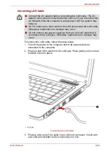
Page 96: ... cable into a LAN hub connector Check with your LAN administrator before connecting to a hub Connect the AC adaptor before connecting the LAN cable The AC adaptor must remain connected during LAN use If you disconnect the AC Adaptor while the computer is accessing a LAN the system may hang up Do not connect any other cable to the LAN jack except the LAN cable Otherwise malfunctions or damage may o...

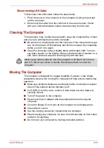
Page 97: ...t clean cloth and wipe the screen gently with the cloth Moving The Computer The computer is designed for rugged durability However a few simple precautions taken when moving the computer will help ensure trouble free operation Make sure all disk activities are terminated before moving the computer Check if the external device indicator is off If a CD DVD is in the drive remove it Also make sure th...

Page 98: ...n the fan first then if necessary lowering the CPU speed Or turns on fan first if necessary lowers CPU processing speed earlier than at Maximum Performance Mode for long battery life These functions are controlled within the Power Options When the CPU temperature falls to a normal range the fan is turned off and the CPU operation returns to standard speed If the CPU temperature reaches an unaccept...

Page 99: ...ed in computer text vary in width Spaces which are created by a space character may also vary depending on line justification and other factors The lowercase l el and the number 1 one are not interchangeable on computers as they are on a typewriter The uppercase O oh and the 0 zero are not interchangeable The CAPS LOCK function key locks only the alphabetic characters in uppercase while the shift ...

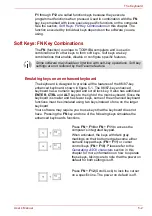
Page 100: ...lso has additional ENTER CTRL and ALT keys to the right of the main keyboard Since the keyboard is smaller and has fewer keys some of the enhanced keyboard functions must be simulated using two keys instead of one on the larger keyboard Your software may require you to use keys that the keyboard does not have Pressing the FN key and one of the following keys simulates the enhanced keyboard s funct...

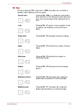
Page 101: ...ng FN F1 enters Lock computer mode To restore your desktop you need to log on again Power plan Pressing FN F2 changes the power settings Sleep Pressing FN F3 switches the system to Sleep Mode Hibernate Pressing FN F4 switches the system to Hibernation Mode Output Pressing FN F5 changes the active display device Brightness down Pressing FN F6 decreases the computer s display panel brightness in ind...

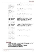
Page 102: ...uchpad Pressing FN F9 enables or disables the touchpad function Zoom Pressing FN SPACE changes the display resolution TOSHIBA zooming utility reduce Pressing FN 1 reduces the icon size on the desktop or the font sizes within one of the supported application windows TOSHIBA zooming utility enlarge Pressing FN 2 enlarges the icon size on the desktop or the font sizes within one of the supported appl...

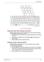
Page 103: ... at their front edge The overlay provides the same functions as the numeric keypad on a standard 101 102 key enhanced keyboard Turning on the overlays The numeric keypad overlay can be used for numeric data input or cursor and page control Arrow mode To turn on the Arrow mode press FN F10 Now try cursor and page control using the keys shown in figure 5 1 Press FN F10 again to turn off the overlay ...

Page 104: ...rcase characters by holding FN SHIFT and pressing a character key 3 Release FN to continue using the overlay Temporarily using overlay overlay off While using the normal keyboard you can temporarily use the keypad overlay without turning it on 1 Press and hold down FN 2 Pressing FN turns on the most recently used overlay If in the Numeric mode you can use the overlay for numeric entry If in the Ar...

Page 105: ...ng ASCII characters Not all ASCII characters can be generated using normal keyboard operation But you can generate these characters using their ASCII codes With the overlay on 1 Hold down ALT 2 Using the overlay keys type the ASCII code 3 Release ALT and the ASCII character appears on the display screen With the overlay off 1 Hold ALT FN 2 Using the overlay keys type the ASCII code 3 Release ALT F...

Page 106: ...ter s operating capability and battery charge status are affected by the power conditions whether an AC adaptor is connected whether a battery is installed and what the charge level is for the battery Power on Power off no operation AC adaptor connected Battery fully charged Operates DC IN Battery LED green DC IN Battery LED green Battery partially charged or no charge Operates Quick Charge DC IN ...

Page 107: ...r Battery charge is exhausted Computer goes into hibernation or shuts down depending on the TOSHIBA power Management Utility Setting No battery installed No operation DC IN Battery LED off Power on Power off no operation Blinking amber Indicates battery charge is below low battery trigger point Amber Indicates the AC adaptor is connected and charging the battery Green Indicates the AC adaptor is c...

Page 108: ...he battery may fail to retain a charge It may not function efficiently over the expected life of the battery and the Battery LED may not indicate a low battery condition Green Indicates power is being supplied to the computer and the computer is turned on Blinking green Indicates the power was turned off while the computer was in Sleep Mode No light Under any other conditions the indicator does no...

Page 109: ...y observe the following advisories Danger Indicates an imminently hazardous situation Which could result in death or serious injury if you do not follow instructions Warning Indicates a potentially hazardous situation Which could result in death or serious injury if you do not follow instructions Caution Indicates a potentially hazardous situation Which if not avoided may result in moderate or min...

Page 110: ...battery pack to abnormal shock vibration or pressure The battery pack s internal protective device will fail causing it to overheat explode ignite or leak caustic liquids possibly resulting in death or serious injury 9 Never let a battery pack become wet A wet battery pack will overheat ignite or rupture possibly resulting in death or serious injury Warning 1 Never allow caustic electrolyte fluid ...

Page 111: ...battery discharge completely Sleep and hibernation will not function and data in memory will be lose Also the computer might register an incorrect time and date In this case connect the AC adaptor to recharge the batteries 7 Never install or remove the battery pack without first turning off the power and disconnecting the AC adaptor Never remove the battery pack while the computer in Hibernate Mod...

Page 112: ...old If the battery is extremely hot it might not charge at all Also to ensure the battery charges to its full capacity charge the battery at room temperature of 10 to 30 C 50 to 86 F The battery is nearly completely discharged Leave the AC adaptor connected for a few minutes and the battery should begin charging The DC IN Battery indicator may show a rapid decrease in battery operating time when y...

Page 113: ...er saving options The computer provides a battery save mode which can be set in Power Options to conserve battery power This mode has the following options CPU Precessing speed Screen brightness Cooling Method System sleep System hibernation Leaving the AC adaptor connected will shorten battery life At least once a month run the computer on battery power until the battery is fully discharged then ...

Page 114: ... time periods Retention Time Extending Battery Life To maximize the life of your battery packs At least once a month disconnect the computer from a power source and operate it on battery power until the battery pack fully discharges Before doing so follow the steps below 1 Turn off the computer s power 2 Disconnect the AC adaptor and turn on the computer s power If it does not turn on then go to S...

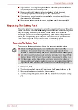
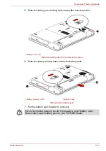
Page 115: ...re operating your computer away from an AC power source This section explains how to remove and install battery packs Removing The Battery Pack To remove a discharged battery follow the steps as detailed below 1 Save your work 2 Turn the computer s power off Make sure the Power indicator is off 3 Remove all cables connected to the computer 4 Turn the computer upside down with the back of the compu...

Page 116: ... to the unlocked position 6 Slide the battery release latch to free the battery pack Removing the battery pack 7 Pull the battery pack forward to remove it 1 Battery Pack Lock 1 Battery Release Latch 2 Battery Pack For environmental reasons do not throw away a spent battery pack Please return spent battery pack to your TOSHIBA dealer ...

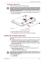
Page 117: ...Windows If the verification is successful the user will be logged into Windows automatically The user can thus avoid having to enter a password or the like which makes the login process easier Enter the password manually To enter a password manually follow these steps 1 Turn on the power as described in Chapter 1 Getting Started The following message appears Enter Current Password 2 Enter the pass...

Page 118: ...On Off You can set up your computer so that power turns off automatically when you close the display panel When you open the panel power turns on in Sleep Mode or Hibernation Mode but not in boot mode System Auto Off This feature turns the system off automatically if it is not used for a set duration The system shuts down in Sleep Mode or Hibernation Mode If you enter the password incorrectly thre...

Page 119: ...play Boot Priority Keyboard LAN and USB to allow specific functions of the computer to be configured In addition there are also three buttons OK Cancel and Apply General This window displays the BIOS EC version and contains two buttons Default and About Setup This field displays the installed BIOS version date and EC version OK Accepts your changes and closes the HW Setup window Cancel Closes the ...

Page 120: ...en or for an external monitor Power On Display This tab allows you to select the display to be used when the computer is started Please note that this setting is only available on standard VGA mode and is not available as part of the Windows Desktop properties Not Registered Changes or remove the password Default Registered Sets the password A dialogue box will appear to allow you to set the passw...

Page 121: ...settings and manually select a boot device by pressing one of the following keys while the computer is booting 1 The floppy diskette drive will be used to start the computer when there is a bootable disk contained in the external drive 2 The optical disc drive will be used to start the computer when there is a bootable disk contained in the drive U Selects the USB diskette drive 1 N Selects the ne...

Page 122: ...ion so that even if your operating system does not support USB devices you can still use a standard USB mouse and keyboard to achieve this you should set the appropriate option s to Enabled If a Supervisor Password has been set manual boot device selection functions may be restricted The boot device selection methods described above will not change the boot priority settings that have been configu...

Page 123: ...is enabled Refer to the section in chapter 6 Retaining Data with Power off Built in LAN This feature enables or disables the Built in LAN Do not install or remove a memory module while Wake up on LAN is enabled The Wake up on LAN function consumes power even when the system is off Leave the AC adaptor connected while using this feature Regarding Wake up on LAN from sleep or hibernation you must ch...

Page 124: ... attached print a copy of the screen using the PRTSC Print Screen key The questions and procedures offered in this chapter are meant as a guide they are not definitive problem solving techniques Many problems can be solved simply but a few may require help from your dealer If you find you need to consult your dealer or others be prepared to describe the problem in as much detail as possible Prelim...

Page 125: ... Check that all connecting cables are correctly and firmly attached Loose cables can cause erroneous or intermittent signals Do any icons light Which ones What color are they Do they stay on or blink Write down what you see Do you hear any beeps if so how many are they long or short and are they high pitched or low pitched In addition is the computer making any unusual noises Write down what you h...

Page 126: ...the Hardware Setup the computer tries to load first from drive A then from drive C or first from drive C then from drive A If any of the following conditions are present the self test failed The computer stops and does not proceed to display information or messages Before using a peripheral device or application software that is not an authorized TOSHIBA part or product make sure the device or sof...

Page 127: ...ceptably high level with either setting the computer will automatically shuts down to prevent any damage in this instance all unsaved data in memory will be lost AC Power If you have trouble turning on the computer with the AC adaptor connected check the DC IN Battery indicator Refer to Chapter 6 Power and Power up Modes for more information Battery If you suspect a problem with the battery check ...

Page 128: ...sure it is securely seated Check the DC IN Battery indicator If it does not glow let the computer charge the battery for at least 20 minutes If the DC IN Battery indicator glows after 20 minutes let the battery continue to charge at least another 20 minutes before turning on the computer If the indicator still does not glow the battery may be at the end of its operating life Replace it If you do n...

Page 129: ...the LCD screen They might have come from contact with the keyboard or touchpad Try wiping the LCD gently with a clean dry cloth If markings remain use LCD cleaner Be sure to let the LCD dry before closing it Problems above remain unresolved or other problems occur Refer to your software s documentation to determine if the software is causing the difficulty Contact your dealer if the problems conti...

Page 130: ...e drawer could block laser light from reading the CD or DVD Make sure there is no obstruction Remove any foreign object Check whether the DVD is dirty If it is wipe it with a cleaning cloth dipped in water or a neutral cleaner See the Media Care section in Chapter 4 for details on cleaning Some CD DVDs run correctly but others do not The software or hardware configuration may be causing a problem ...

Page 131: ...the computer during writing Do not connect disconnect external devices or install remove internal cards during writing If problems persist contact your dealer Problem Procedure Problem Procedure Monitor does not turn on Make sure that the external monitor s power switch is on Confirm that the external monitor s power cable is plugged into a working power outlet No display Try adjusting the contras...

Page 132: ...Drive does not operate There may be a faulty cable connection Check the connection to the computer and to the drive Some programs run correctly but others do not The software or hardware configuration may be causing a problem Make sure the hardware configuration matches your software needs You cannot access the external diskette drive Try another diskette If you can access the diskette the origina...

Page 133: ... Panel Hardware and Sound Mouse to access it When the reaction of touchpad is sensitive to slow Adjust the touch Sensitivity 1 Open the Control Panel 2 Click the Hardware and Sound icon 3 Click the Mouse icon 4 Click the Device Setting tab 5 Click the Settings button 6 The Properties for Synaptics touchpad on PS 2 port screen appears Double click Sensitivity in the Select an item section on the le...

Page 134: ...or FN 4 to increase Check the software volume settings Make sure the headphone connection is secure Check Windows Device Manager Make sure the sound function is enabled and that settings for I O address Interrupt level and DMA are correct for your software and do not conflict with other hardware devices that you may have connected to the computer If problems persist contact your dealer Problem Pro...

Page 135: ... playing a selection or finished playing a selection Close Windows Media Player before you select sleep hibernation If problems persist contact your dealer Problem Procedure Cannot access LAN Check for a firm cable connection between the LAN jack and the LAN HUB Wake up on LAN Make sure the AC adaptor is connected The does not work Wake up on LAN function consumes power even when the system is off...

Page 136: ...r best resource for current information and support Where to Write If you are still unable to solve the problem and suspect that it is hardware related write to TOSHIBA at the location listed in the enclosed warranty booklet or visit http www toshiba europe com on the Internet Problem Procedure The following message appears when executing Recovery Media Creator The Recovery Media Creator can not b...

Page 137: ...cal specifications Environmental Requirements Power Requirements Operating Non operating Ambient temperature 5 C to 35 C 20 C to 60 C Relative humidity 20 to 80 10 to 90 Altitude from sea level 0 to 3 000 meters 0 to 10 000 meters AC adaptor 100 240 volts AC 50 or 60 hertz cycles per second Computer 19V DC ...

Page 138: ... computer that supports that mode Video mode Video mode settings are configured via the Screen Resolution dialog To open the Screen Resolution dialog click Start Control Panel Appearance and Personalization Display Change display settings Due to the display panel s increased resolution lines may appear broken in when displaying images in full screen text mode If you are running some application fo...

Page 139: ...d 5 GHz band local radio regulations may impose a number of limitations to the use of wireless communication equipment The range of the wireless signal is related to the transmit rate of the wireless communication Communications at lower transmit range may travel larger distances Form Factor PCI Express Mini Card Compatibility IEEE 802 11 Standard for Wireless LANs Wi Fi Wireless Fidelity certifie...

Page 140: ...02 11 Revision B G and N 1 Factory set default channels 2 The band width and the channel which can be used depends on the installed wireless LAN module And the approved channels on using are different at each country or region The channel configuration is managed as follows For wireless clients that operate in a Wireless LAN Infrastructure the Wireless LAN module will automatically start operation...

Page 141: ...Point device 5 GHz Band Channels Sets Wireless IEEE 802 11 Revision A and N 1 Factory set default channels Frequency Range Channel ID 5150 5850 MHz 34 5170 2 36 5180 2 38 5190 2 40 5200 2 42 5210 2 44 5220 2 46 5230 2 48 5240 2 52 5260 2 56 5280 2 60 5300 2 64 5320 2 100 5500 2 104 5520 2 108 5540 2 112 5560 2 116 5580 2 120 5600 2 124 5620 2 128 5640 2 132 5660 2 136 5680 2 140 5700 2 149 5745 2 ...

Page 142: ...less LAN Infrastructure the Wireless LAN module will automatically start operation at the channel identified by the Wireless LAN Access Point When roaming between different access points the station can dynamically switch to another channel if required In a Wireless LAN Access Point the Wireless LAN module will use the factory set default channel printed in bold unless the LAN Administrator select...

Page 143: ...onfiguration must be 2 15P 250V or 1 15P 125V while three pin be 6 15P 250V or 5 15P 125V as designated in the U S National Electrical code handbook and the Canadian Electrical Code Part II Length Minimum 1 7 meters Wire size Minimum 0 75 mm2 Current rating Minimum 2 5 amperes Voltage rating 125 or 250V AC depending on country region s power standards Europe Austria OVE Italy IMQ Belgium CEBEC The...

Page 144: ...he following illustrations show the plug shapes for USA Australia Canada United Kingdom Europe and China USA United Kingdom UL approved Australia Canada CSA approved AS approved BS approved Europe CCC approved China Approved by the appropriate agency ...

Page 145: ...er instead of AC power use of certain multimedia computer generated graphics or video applications use of standard telephone lines or low speed network connections use of complex modeling software such as high end computer aided design applications use of several applications or functionalities simultaneously use of computer in areas with low air pressure high altitude 1 000 meters or 3 280 feet a...

Page 146: ...e used by the graphics system for graphics performance and therefore reduce the amount of main system memory available for other computing activities The amount of main system memory allocated to support graphics may vary depending on the graphics system applications utilized system memory size and other factors Computers configured with a 32 bit operating system can address up to 3 GB of system m...

Page 147: ...hics processor unit GPU performance may vary depending on product model design configuration applications power management settings and features utilized GPU performance is only optimized when operating in AC power mode and may decrease considerably when operating in battery power mode Total Available Graphics Memory is the total of as applicable Dedicated Video Memory System Video Memory and Shar...

Page 148: ...User s Manual E 4 Legal Footnotes Copy Protection Copy protection technology included in certain media may prevent or limit recording or viewing of the media ...

Page 149: ...form to the address below To register the theft online please follow these procedures Visit http www toshiba europe com on the Internet In the product area choose Computer Systems In the Computer Systems page open the Support Downloads menu and choose the Stolen Units Database option Your entries are used to track your computer at our service points Always take care of your computer and try to pre...

Page 150: ...rt Blumenstrasse 26 93055 Regensburg Germany Fax number 49 0 941 7807 921 Owner s details Country stolen Machine type e g Satellite C640 C640D Satellite Pro C640 C64 0D Series Model number e g PSA30EYXT Serial number e g 12345678G Date stolen Year Month Day Last name first name Company Street Postal Code City Country Phone Fax ...

Page 151: ...nd CD compact disc CD ROM Compact Disc Read Only Memory CD RW Compact Disc ReWritable CMOS complementary metal oxide semiconductor CPU central processing unit CRT cathode ray tube DC direct current DDC display data channel DIMM dual inline memory module DMA direct memory access DOS disk operating system DVD digital versatile disc DVD R Digital Versatile Disc Recordable DVD RAM Digital Versatile Di...

Page 152: ...RTC real time clock SCSI small computer system interface SD Secure Digital SDHC Secure Digital High Capacit SDXC Secure Digital Extended Capacity SDRAM synchronous dynamic random access memory SIO serial input output SLI Scalable Link Interface TFT thin film transistor UART universal asynchronous receiver transmitter USB Universal Serial Bus UXGA ultra extended graphics array VESA Video Electronic...

Page 153: ...antistatic A material used to prevent the buildup of static electricity application A group of programs that together are used for a specific task such as accounting financial planning spreadsheets word processing and games ASCII American Standard Code for Information Interchange ASCII code is a set of 256 binary codes that represent the most commonly used letters numbers and symbols async Short f...

Page 154: ...eads data from main memory it stores a copy of this data in cache memory The next time the CPU needs that same data it looks for it in the cache memory rather than the main memory which saves time The computer has two cache levels Level one is incorporated into the processor and level two resides in external memory capacity The amount of data that can be stored on a magnetic storage device such as...

Page 155: ...m which make up the whole system Composite Video YUV A standard video signal used to transmit images e g from a VCR to a TV computer program A set of instructions written for a computer that enable it to achieve a desired result computer system A combination of hardware software firmware and peripheral components assembled to process data into useful information configuration The specific componen...

Page 156: ...sound files disk drive The device that randomly accesses information on a disk and copies it to the computer s memory It also writes data from memory to the disk To accomplish these tasks the unit physically rotates the disk at high speed past a read write head disk storage Storing data on magnetic disk Data is arranged on concentric tracks much like a phonograph record display A CRT LCD or other ...

Page 157: ...elete escape guard time A time before and after an escape code is sent to the modem which distinguishes between escapes that are part of the transmitted data and escapes that are intended as a command to the modem escape 1 A code ASCII code 27 signaling the computer that what follows are commands used with peripheral devices such as printers and modems 2 A means of aborting the task currently in p...

Page 158: ...y the computer itself external disk drives etc See also software and firmware hertz A unit of wave frequency that equals one cycle per second hexadecimal The base 16 numbering system composed of the digits 0 through 9 and the letters A B C D E and F host computer The computer that controls regulates and transmits information to a device or another computer hot key The computer s feature in which c...

Page 159: ...two points of a circuit K K Taken from the Greek word kilo meaning 1000 often used as equivalent to 1024 or 2 raised to the 10th power See also byte and kilobyte KB See kilobyte keyboard An input device containing switches that are activated by manually pressing marked keys Each keystroke activates a switch that transmits a specific code to the computer For each key the transmitted code is in turn...

Page 160: ...anumeric characters or graphic images See also CRT motherboard A name sometimes used to refer to the main printed circuit board in processing equipment It usually contains integrated circuits that perform the processor s basic functions and provides connectors for adding other boards that perform special functions Sometimes called a main board N non system disk A formatted floppy diskette you can ...

Page 161: ...nt interconnect An industry standard 32 bit bus peripheral device An I O device that is external to the central processor and or main memory such as a printer or a mouse Péritel Péritel is a 21 pin connecting cable port system that allows images and high quality stereo sound including Dolby Pro Logic sound formats to be sent from one audio visual device to another It is also known as a SCART conne...

Page 162: ...N jack ROM Read Only Memory A nonvolatile memory chip manufactured to contain information that controls the computer s basic operation You cannot access or change information stored in ROM S S Video Short for Super Video a type of connection used by S VHS videocassette players camcorders DVD players etc to transmit high quality video signals SCSI Small Computer System Interface is an industry stan...

Page 163: ...em is contained in two hidden files and the COMMAND COM file You can boot a computer using a system disk Also called an operating system disk T terminal A typewriter like keyboard and CRT display screen connected to the computer for data input output TFT display A liquid crystal display LCD made from an array of liquid crystal cells using active matrix technology with thin film transistor TFT to d...

Page 164: ...ing it off window A portion of the screen that can display its own application document or dialog box Often used to mean a Microsoft Windows window Wireless LAN Local Area Network LAN through wireless communication write protection A method for protecting a floppy diskette from accidental erasure ...

Page 165: ...operating time 6 8 problems 8 4 replacing 6 10 safety instructions vi 6 4 save mode 3 6 Boot priority HW Setup 7 3 Bridge media slot function 3 11 C Checklist equipment 1 1 problems 8 1 8 3 Cleaning the computer 4 30 D DC IN 2 1 connecting 1 5 indicator 2 7 6 2 location 2 1 Display 2 5 2 6 3 3 E 3 automatic power off 3 6 brightness down 5 3 brightness up 5 3 controller B 1 HW Setup 7 2 opening 1 6...

Page 166: ...7 1 H Hard disk drive automatic power off 3 6 capacity E 3 problems 8 6 Headphone 3 4 problems 8 11 Hibernation Mode 3 7 problems 8 12 setting 1 10 Hot keys 3 6 brightness down 5 3 brightness up 5 3 hibernate 5 3 lock 5 3 output 5 3 power plan 5 3 sleep 5 3 sound mute 5 3 TOSHIBA zooming utility enlarge 5 4 TOSHIBA zooming utility reduce 5 4 touchpad 5 4 Volume Down 5 4 Volume Up 5 4 wireless 5 4 ...

Page 167: ... E 2 expansion 3 10 3 17 installing module 3 17 module cover 2 4 removing module 3 19 Memory cards problems 8 8 Microphone 3 4 built in 2 5 function 4 26 port 2 2 problems 8 11 Microprocessor See Processor Moving the computer 4 30 N Numeric keypad See Keypad overlay O Optical disc drive 2 1 Function 4 8 safety instructions xi P Password HW Setup 7 2 power on 3 6 problems 8 5 starting the computer ...

Page 168: ... Wireless LAN 8 12 Processor 3 1 R Real Time Clock battery See Battery Recovery media problems 8 13 Restarting the computer 1 11 S Security lock attaching 3 22 Shut Down Mode boot mode 1 8 Sleep Mode 3 7 problems 8 12 setting 1 8 Soft keys emulating keys on enhanced keyboard 5 2 scroll lock 5 2 Sound system 3 5 headphone 2 2 3 4 microphone 2 2 2 5 speaker 2 6 T TOSHIBA Accessibility 3 8 TOSHIBA As...

Page 169: ...ation F 2 TOSHIBA zooming utility 3 7 Touchpad 2 6 control buttons 2 6 problems 8 10 using 4 1 U USB 3 4 HW Setup 7 4 problems 8 11 USB mouse problems 8 10 V Video RAM 3 1 W Web camera 2 5 3 5 using 4 2 Wireless LAN 3 5 E 3 function 4 27 problems 8 12 ...

Reviews: