background image

8.

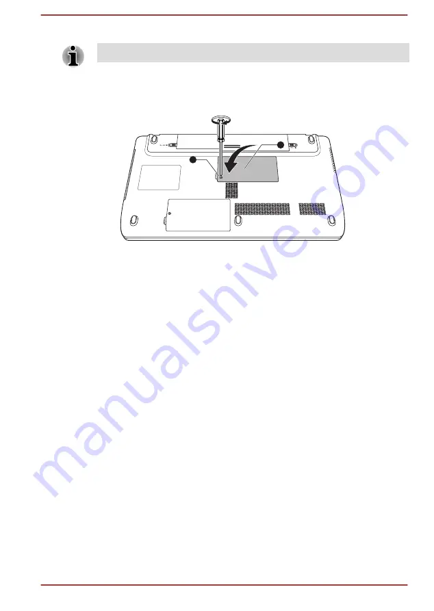
Seat the memory module cover in place and secure it with the screw.

Take care to ensure that the memory module cover is firmly closed.

Figure 3-13 Seating the memory module cover (Satellite L770/L775/L770D/

L775D/satellite Pro L770/L775/L770D/L775D)

1

2

1. Screw

2. Memory module cover

9.

Install the battery pack - refer to 

Replacing the battery pack

 section in

Chapter 5, Power and Power-Up Modes, if required.

10. Turn your computer over.
11. Turn the computer on and make sure the added memory is recognized

- to confirmed it, 

Start -> Control Panel -> System and Security ->

System

 icon.

Removing a memory module

To remove the memory module, follow the steps as detailed below:
1.

Shut down the computer - make sure the 

Power

 indicator is off (refer

to the 

Turning off the power

 section in Chapter 1, Getting Started if

required).

2.

Remove the AC adaptor and all cables and peripherals connected to
the computer.

3.

Close the display panel.

4.

Turn the computer upside down and remove the battery pack.

5.

Loosen the screw securing the memory module cover in place -
please note that the screw is attached to the cover in order to prevent
them from being lost.

6.

Slide your fingernail or a thin object under the cover and lift it off.

7.

Push the latches away from the module in order to release it - a spring
will force one end of the module up at an angle.

User's Manual

3-35

Summary of Contents for Satellite L770

Page 1: ...User s Manual Satellite C670 C675 C670D C675D Satellite Pro C670 C675 C670D Satellite L770 L775 L770D L775D Satellite Pro L770 L775 L770D L775D Series ...

Page 2: ... Operating Basics Using the Touch Pad 3 1 The Keyboard 3 1 Optical disc drives 3 5 TOSHIBA VIDEO PLAYER 3 15 Using WinDVD BD for TOSHIBA 3 20 Wireless communications 3 22 LAN 3 26 Optional devices 3 28 Memory media slot 3 28 Memory media 3 29 Media care 3 30 Inserting a memory media 3 31 Removing a memory media 3 31 Additional memory module 3 32 External monitor 3 36 HDMI 3 37 Security lock 3 41 O...

Page 3: ...L770 L775 L770D L775D 5 2 Monitoring of power condition for Satellite C670 C675 C670D C675D Satellite Pro C670 C675 C670D 5 4 Monitoring of power condition for Satellite L770 L775 L770D L775D satellite Pro L770 L775 L770D L775D 5 5 Battery 5 6 Power up modes 5 12 Panel power on off 5 12 System automatic Sleep Hibernation 5 12 Chapter 6 Troubleshooting Problem solving process 6 1 Hardware and syste...

Page 4: ... descriptions it contains are accurate for your computer at the time of this manual s production However succeeding computers and manuals are subject to change without notice TOSHIBA assumes no liability for damages incurred directly or indirectly from errors omissions or discrepancies between the computer and the manual Trademarks Intel Intel SpeedStep Intel Core and Centrino are trademarks or re...

Page 5: ...o or television reception which can be determined by turning the equipment off and on the user is encouraged to try to correct the interference by one or more of the following measures Reorient or relocate the receiving antenna Increase the separation between the equipment and receiver Connect the equipment into an outlet on a circuit different from that to which the receiver is connected Consult ...

Page 6: ...omplies with the Ecodesign Directive 2009 125 EC ErP and its related implementing measures This product and the original options are designed to observe the related EMC Electromagnetic Compatibility and safety standards However TOSHIBA cannot guarantee that this product still observes these EMC standards if options or cables not produced by TOSHIBA are connected or implemented In this case the per...

Page 7: ... aircraft the manufacturer or airline respectively should be asked for permission before use of this product Furthermore for general safety reasons the use of this product in environments with explosive atmospheres is not permitted Canadian regulatory information Canada only This digital apparatus does not exceed the Class B limits for radio noise emissions from digital apparatus as set out in the...

Page 8: ...f batteries and or accumulators The crossed out wheeled dust bin symbol indicates that batteries and or accumulators must be collected and disposed of separately from household waste If the battery or accumulator contains more than the specified values of lead Pb mercury Hg and or cadmium Cd defined in the Battery Directive 2006 66 EC then the chemical symbols for lead Pb mercury Hg and or cadmium...

Page 9: ...ba europe com computers info reach for information about the presence in our articles of substances included on the candidate list according to article 59 1 of Regulation EC No 1907 2006 REACH in a concentration above 0 1 weight by weight Following information is only for Turkey Compliant with EEE Regulations TOSHIBA meets all requirements of Turkish regulation 26891 Restriction of the use of cert...

Page 10: ... of the required label on the optical disc drive 2 HITACHI LG Data Storage Inc DVD SuperMulti with Double Layer GT30N 30F Blu ray Combo CT31F Blu ray Writer BT11F Hitachi LG Data Storage Inc 22 23 KAIGAN 3 CHOME MINATO KU TOKYO 108 0022 JAPAN 3 TOSHIBA Samsung Storage Technology DVD SuperMulti with Double Layer TS L633F L633W TOSHIBA SAMSUNG STORAGE TECHNOLOGY KOREA CORPORATION 416 MEATAN 3 DONG Y...

Page 11: ...aser system and is classified as a CLASS 1 LASER PRODUCT To use this model properly read the instruction manual carefully and keep this manual for your future reference In case of any trouble with this model please contact your nearest AUTHORIZED service station To prevent direct exposure to the laser beam do not try to open the enclosure User s Manual xi ...

Page 12: ...cronyms are also defined in the Glossary Icons Icons identify ports dials and other parts of your computer The indicator panel also uses icons to identify the components it is providing information on Keys The keyboard keys are used in the text to describe many computer operations A distinctive typeface identifies the key top symbols as they appear on the keyboard For example ENTER identifies the ...

Page 13: ...quipment or failure to follow instructions may cause data loss or damage your equipment Please read A note is a hint or advice that helps you make best use of your equipment Terminology This term is defined in this document as follows Start The word Start refers to the button in Windows 7 HDD or Hard disk drive Some models are equipped with a Solid State Drive SSD instead of a hard disk drive In t...

Page 14: ...e computer Always operate your computer on a hard flat surface Using your computer on a carpet or other soft material can block the vents Always provide sufficient space around the computer Overheating your computer or AC adaptor could cause system failure computer or AC adaptor damage or a fire possibly resulting in serious injury Creating a computer friendly environment Place the computer on a f...

Page 15: ...n become hot The surface of the AC adaptor can become hot when in use but this condition does not indicate a malfunction If you need to transport the AC adaptor you should disconnect it and let it cool before moving it Do not lay the AC adaptor on a material that is sensitive to heat as the material could become damaged Pressure or impact damage Do not apply heavy pressure to the computer or subje...

Page 16: ...sure you have all the following items TOSHIBA Portable Personal Computer AC adaptor and power cord 2 pin plug or 3 pin plug Battery pack Documentation User Information Guide Instruction Manual for Safety and Comfort If any of the items are missing or damaged contact your dealer immediately Software The following Windows operating system and utility software are pre installed Windows 7 TOSHIBA Reco...

Page 17: ...fortable and productive while using a notebook computer By following the recommendations in it you may reduce your chance of developing a painful or disabling injury to your hand arms shoulders or neck This section provides basic information to start using your computer It covers the following topics Connecting the AC adaptor Opening the display Turning on the power Starting up for the first time ...

Page 18: ...se of an incompatible adaptor Never plug the AC adaptor into a power source that does not correspond to both the voltage and the frequency specified on the regulatory label of the unit Failure to do so could result in a fire or electric shock possibly resulting in serious injury Always use or purchase power cables that comply with the legal voltage and frequency specifications and requirements in ...

Page 19: ...r detailed precautions and handling instructions 1 Connect the power cord to the AC adaptor Figure 1 1 Connecting the power cord to the AC adaptor 2 pin plug Figure 1 2 Connecting the power cord to the AC adaptor 3 pin plug Either a 2 pin or 3 pin adaptor cord will be included with the computer depending on the model 2 Connect the AC adaptor s DC output plug to the DC IN 19V jack on the left of th...

Page 20: ...adjusted to provide optimum clarity Figure 1 4 Opening the display panel Satellite L770 L775 L770D L775D Satellite Pro L770 L775 L770D L775D 1 1 Display panel Use reasonable care when opening and closing the display panel Opening it vigorously or slamming it shut could damage the computer Be careful not to open the display panel too far as this could put stress on the display panel s hinges and ca...

Page 21: ...ower Up Modes for more information After you turn on the power for the first time do not turn it off until you have set up the operating system Volume cannot be adjusted during Windows Setup 1 Open the display panel 2 Press and hold the computer s power button for two or three seconds Figure 1 6 Turning on the power Satellite L770 L775 L770D L775D Satellite Pro L770 L775 L770D L775D 1 1 Power butt...

Page 22: ...ould cause loss of data Never turn off the power disconnect an external storage device or remove storage media during data read write Doing so can cause data loss 3 Click Start 4 Click the Shut down button 5 Turn off any peripheral devices connected to your computer Do not turn the computer or peripheral devices back on immediately wait a short period to avoid any potential damage Sleep Mode If yo...

Page 23: ...of time Please note that keyboard keys can only be used if the Wake up on Keyboard option is enabled within the HW Setup utility If the computer enters Sleep Mode while a network application is active the application might not be restored when the computer is next turned on and the system returns from Sleep Mode To prevent the computer from automatically entering Sleep Mode disable Sleep Mode with...

Page 24: ...diately after shutting down Memory circuits are exposed to static electricity or electrical noise Hibernation Mode The Hibernation Mode feature saves the contents of memory to the hard disk drive when the computer is turned off so that the next time it is turned on the previous state is restored Please note that the Hibernation Mode feature does not save the status of any peripheral devices connec...

Page 25: ... follow the steps as described below 1 Click Start and click the Control Panel 2 Click System and Security and click Power Options 3 Click Choose what the power buttons do or Choose what closing the lid does 4 Enable the desired Hibernation Mode settings for When I press the power button and When I close the lid 5 Click the Save changes button Data save in Hibernation Mode When you turn off the po...

Page 26: ...arrow icon and then select Restart from the menu Press CTRL ALT and DEL simultaneously once to display the menu window then select Restart from the Shut down options Press the power button and hold it down for five seconds Once the computer has turned itself off wait between ten and fifteen seconds before turning the power on again by pressing the power button User s Manual 1 11 ...

Page 27: ...Tour for Satellite C670 C675 C670D C675D Satellite Pro C670 C675 C670D Front with the display closed The following figure shows the computer s front with its display panel in the closed position Figure 2 1 Front of the computer with display panel closed 1 2 1 DC IN Battery indicator 2 Power indicator DC IN Battery indica tor The DC IN Battery indicator shows the status of the battery s charge gree...

Page 28: ... purchased DC IN 19V jack The AC adaptor connects to this jack in order to power the computer and charge its internal batteries Please note that you should only use the model of AC adaptor supplied with the computer at the time of purchase using the wrong AC adaptor can cause damage to the computer Cooling vents The cooling vents help the processor avoid overheating Do not block the cooling vents ...

Page 29: ...l Serial Bus ports which comply to the USB 2 0 standard are provided on the left side of the computer Memory media slot This slot lets you insert an SD SDHC SDXC memory card miniSD microSD Card and MultiMediaCard Refer to the Optional devices section in Chapter 3 Operating Basics for more information Microphone jack A 3 5 mm mini microphone jack enables connection of a monaural microphone Headphon...

Page 30: ...ws staples and paper clips out of the Memory media slot and USB ports Foreign metal objects can create a short circuit which can cause damage and fire possibly resulting in serious injury Back The following figure shows the computer s back Figure 2 4 The back of the computer 1 1 Battery pack Battery pack The rechargeable lithium ion battery pack provides power to the computer when the AC adaptor i...

Page 31: ...ch into its Unlock position in order to release the battery pack for removal For more detailed information on removing the battery pack please refer to Chapter 5 Power and Power Up Modes Memory module slot The memory module slot allows for the installation replacement and removal of additional memory module 1 GB 2 GB or 4 GB memory modules can be installed in the computer s two memory slots for a ...

Page 32: ...the computer with the display panel open In order to open the display lift the display panel up and position it at a comfortable viewing angle for you Figure 2 6 The front of the computer with the display panel open 7 8 5 2 1 4 3 6 11 10 9 11 6 1 Display screen 7 Power button 2 Web Camera LED 8 Keyboard 3 Web Camera 9 Touch Pad 4 Microphone 10 Touch Pad control buttons 5 Bluetooth antenna and Wire...

Page 33: ...ch as Windows Live Messenger TOSHIBA Web Camera Application will help you to add various video effects to your video or photograph Enables the transmission of video and use of video chat via the internet using specialized applications Some models are equipped with a Web Camera Please refer to the Web Camera Application Online Help for details Microphone A built in microphone allows you to import a...

Page 34: ...yboard section in Chapter 3 Operating Basics for details Touch Pad The Touch Pad located in the palm rest is used to control the movement of the on screen pointer For more information please refer to the Using the Touch Pad in Chapter 3 Operating Basics Touch Pad control buttons The control buttons located below the Touch Pad allow you to select menu items or manipulate text and graphics as design...

Page 35: ...ns turned off Battery indicator The Battery indicator shows the condition of the battery s charge white indicates the battery is fully charged amber indicates the battery is charging and blinking amber indicates a low battery condition Please refer to Chapter 5 Power and Power Up Modes for more information on this feature Hard Disk Drive Opti cal Disc Drive indica tor The Hard Disk Drive Optical D...

Page 36: ...only use the model of AC adaptor supplied with the computer at the time of purchase using the wrong AC adaptor can cause damage to the computer Cooling vents The cooling vents help the processor avoid overheating Do not block the cooling vents Keep foreign metal objects such as screws staples and paper clips out of the cooling vents Foreign metal objects can create a short circuit which can cause ...

Page 37: ... HDMI out port can connect with Type A connector HDMI cable Some models are equipped with an HDMI out port Memory media slot This slot lets you insert an SD SDHC SDXC memory card miniSD microSD Card Memory Stick Memory Stick PRO and MultiMediaCard Refer to the Optional devices section in Chapter 3 Operating Basics for more information Right side The following figure shows the computer s right side...

Page 38: ...B and 5 2GB DVD RAM media cannot be read from or written to Security lock slot A security cable can be attached to this slot and then connected to a desk or other large object in order to deter theft of the computer Please note that it is not possible to confirm the operation of all functions of all USB devices that are available In view of this it may be noted that some functions associated with ...

Page 39: ... the computer You should ensure that the display is closed before the computer is turned over to avoid causing any damage Figure 2 11 The underside of the computer 1 2 3 4 1 Battery lock 3 Memory module slot 2 Battery release latch 4 Cooling vents Product appearance depends on the model you purchased Battery lock Slide the battery lock to release the battery pack ready for removal Battery release ...

Page 40: ...asics Cooling vents The cooling vents help the processor avoid overheating Do not block the cooling vents Keep foreign metal objects such as screws staples and paper clips out of the cooling vents Foreign metal objects can create a short circuit which can cause damage and fire possibly resulting in serious injury Carefully clean the dust on the cooling vents surface using a soft cloth Front with t...

Page 41: ...chased Display screen 43 9 cm 17 3 LCD screen 16 million colors configured with the following resolution HD 1600 horizontal x 900 vertical pixels Please be aware that when the computer is operating on the AC adaptor the image displayed on the internal screen will be somewhat brighter than when it operates on battery power This difference in brightness levels is intended to save power when operatin...

Page 42: ...ore information Do not point the web camera directly at the sun Do not touch or press strongly on the web camera lens Doing so may reduce image quality Use an eyeglass cleaner cleaner cloth or other soft cloth to clean the lens if it becomes dirty When recording in dimly lit environments select Night Mode which allows for brighter images with less noise Wireless LAN anten nas Some computers in thi...

Page 43: ...ble or disable the Touch Pad function Internal Hardware Components This section describes the internal hardware components of your computer The actual specifications may vary depending on the model you purchased CPU The processor type varies depending on model To check which type of processor is included in your model open the TOSHIBA PC Diagnostic Tool Utility by clicking Start All Programs TOSHI...

Page 44: ... on a bitmap display The amount of Video RAM available is dependent on the computer s system memory Start Control Panel Appearance and Personalization Display Adjust resolution The amount of Video RAM can be verified by clicking the Advanced settings button in the Screen Resolution window Legal Footnote Memory Main System For more information regarding Memory Main System please refer to the Legal ...

Page 45: ...edia Control Panel You can access this control panel in one of the following ways Click Start Control Panel Select Large icons or Small icons in View by and then click Intel R Graphics and Media Right click on the desktop and click Graphics Properties In this control panel 1 Select Basic Mode and click OK 2 Click Power 3 Select On battery from the drop down menu in Power Source and then select the...

Page 46: ...er In this control center 1 Select PowerPlay under Power 2 Select the Enable PowerPlay check box and then select the Enable Vari Bright check box If you want to improve the picture quality under the conditions mentioned above adjust the setting towards Maximize Quality or disable this feature User s Manual 2 20 ...

Page 47: ...nction Some models are equipped with the Touch Pad ON OFF button The two buttons below the Touch Pad are used like the buttons on a standard mouse press the left button to select a menu item or to manipulate text or graphics designated by the pointer and press the right button to display a menu or other function depending on the software you are using The Keyboard The computer s keyboard layouts a...

Page 48: ...L770 L775 L770D L775D Satellite Pro L770 L775 L770D L775D 1 2 1 CAPS LOCK indicator 2 NUM LOCK indicator CAPS LOCK This indicator glows green when letter keys are locked into their uppercase format NUM LOCK When the NUM LOCK indicator glows you can use the number keys on the keyboard for number entry Function keys F1 F9 The function keys not to be confused with the special FN key are the nine keys...

Page 49: ...enable or disable certain features of the computer The Hot key functions can be performed using either the Hot Key Cards or by pressing the associated Hot keys pressing FN a function or ESC key Hot Key Cards The Hot Key Cards are normally hidden from view The Cards appear when you press the FN key To use the Hot Key Cards 1 Press and hold the FN key The TOSHIBA Flash Cards appear along the top of ...

Page 50: ...esolution of the external display device Brightness Down Pressing FN F6 decreases the computer s display panel brightness in individual steps Brightness Up Pressing FN F7 increases the computer s display panel brightness in individual steps Wireless Pressing FN F8 switches the active wireless devices If no wireless communication device is installed no dialog box will appear Touch Pad Pressing FN F...

Page 51: ...ating ASCII characters Not all ASCII characters can be generated using normal keyboard operation but you are able to generate these characters using their specific ASCII codes 1 Hold down ALT key 2 Using the numeric keypad type the ASCII code of the character you require 3 Release ALT the ASCII character will appear on the display screen Optical disc drives The computer may be installed with a DVD...

Page 52: ...based programs You can run either 12 cm 4 72 or 8 cm 3 15 discs without an adaptor Use the DVD playback application to view DVD Video discs If you have an Optical disc drive refer also to the Writing CD DVD Blu ray discs section for precautions on writing to CDs DVD Blu ray discs To load discs follow the steps as detailed below 1 When the computer s power is on press the eject button to open the d...

Page 53: ... the disc tray to make sure there are no such objects before closing the drive 4 Press gently at the center of the disc until you feel it click into place The disc should lie below the top of the spindle flush with the spindle base 5 Push the center of the disc tray to close it Press gently until it locks into place If the disc is not seated properly when the disc tray is closed the disc might be ...

Page 54: ...lip into the eject hole near the eject button Figure 3 7 Manual release with the eject hole Satellite L770 L775 L770D L775D satellite Pro L770 L775 L770D L775D 1 Φ1 0mm 1 Eject hole Turn off the power before you use the eject hole If the disc is spinning when you open the disc tray the disc could fly off the spindle and cause injury Writable discs This section describes the types of writable discs...

Page 55: ...or to a live power socket It is possible that if data is written while powered by the battery pack the write process may sometimes fail due to low battery power in these instances data loss may occur Important message Before you write or rewrite to any of the media supported by the DVD Super Multi Drive or Blu ray Combo Blu ray Writer drive please read and follow all of the setup and operating ins...

Page 56: ...HIBA guarantee the operation quality or performance of any disc CD R TAIYO YUDEN CO Ltd MITSUBISHI KAGAKU MEDIA CO LTD CD RW Multi Speed High Speed and Ultra Speed MITSUBISHI KAGAKU MEDIA CO LTD DVD R DVD Specifications for Recordable Disc for General Version 2 0 TAIYO YUDEN Co Ltd for 8x and 16x speed media MITSUBISHI KAGAKU MEDIA CO LTD for 8x and 16x speed media Hitachi Maxell Ltd for 8x and 16...

Page 57: ...lowing points while you write or rewrite data to a media Always copy data from the hard disk drive to the optical media do not use the cut and paste function as the original data will be lost if there is a write error Do not perform any of the following actions Change users in the Operating Systems Operate the computer for any other function including such tasks as using a mouse or Touch Pad or cl...

Page 58: ...u cannot use TOSHIBA Disc Creator s Audio CD function to record music to DVD R DVD R DL DVD RW DVD R DVD R DL or DVD RW media Do not use the Disc Backup function of TOSHIBA Disc Creator in order to copy DVD Video or DVD ROM material that has copyright protection DVD RAM discs cannot be backed up using the Disc Backup function of TOSHIBA Disc Creator You cannot back up CD ROM CD R or CD RW media to...

Page 59: ... DVD R DL DVD RW DVD R DVD R DL or DVD RW disc be sure to use the same type of disc You cannot partially delete any data written to a CD RW DVD RW or DVD RW disc Data Verification To verify that data has been written or rewritten correctly to a data CD DVD you should follow the steps below before you begin the write rewrite process 1 Click Start All Programs TOSHIBA CD DVD Applications Disc Creato...

Page 60: ...ck the Go to menu editing button 9 Click the Burn button How to learn more about Corel Digital Studio Please refer to the Help and Manual files for additional Corel Digital Studio information To open the Corel Digital Studio Manual press the F1 key when the Corel Digital Studio is launched Important information for use Note the following limitations when you write Video DVD or Blu ray Disc movie f...

Page 61: ...to the computer Use the Mode control button and Audio Video control button to reproduce music or voice Open the DVD Blu ray drive Install remove or connect external devices including the following memory media card USB device external display optical digital devices Please verify your disc after recording important data Not support to output VCD and SVCD format Force eject disc About recorded DVDs...

Page 62: ... when playing video Power saving features may interfere with smooth playback When playing DVD Video using battery power set the Power Options to Balance The screen saver is disabled during video playback using the TOSHIBA VIDEO PLAYER The computer will not automatically go into Hibernation Sleep or shut down mode Do not configure the Display automatic power off function to run while the TOSHIBA VI...

Page 63: ...annot be displayed simultaneously in clone mode on both the computer s display panel and an external display Do not change the screen resolution while running the TOSHIBA VIDEO PLAYER Do not change the display device while running the TOSHIBA VIDEO PLAYER Starting TOSHIBA VIDEO PLAYER Use the following procedure to start TOSHIBA VIDEO PLAYER 1 Insert an DVD Video in the optical disc drive while Wi...

Page 64: ...ization The TOSHIBA VIDEO PLAYER is intended for playing DVD Video DVD VR and video files and for viewing 2D home video content in 3D The 3D playback of any video content not created by the user may require the permission of third parties where such content is protected by copyright The protection of intellectual property rights is essential for Toshiba In this respect Toshiba underlines that the ...

Page 65: ...Only Side by Side and Interleave 3D video formats are supported for playback of 3D video content Starting TOSHIBA VIDEO PLAYER Use the following procedure to start TOSHIBA VIDEO PLAYER 1 Insert an DVD Video in the DVD Blu ray drive while Windows 7 is running When a DVD Video disc is set in the Blu ray drive for models with Blu ray Writer drive or Blu ray Combo drive TOSHIBA VIDEO PLAYER starts aut...

Page 66: ...rers directly Make sure to connect the computer s AC adapter when playing a Blu ray Disc WinDVD BD supports AACS Advanced Access Control System copy protection technology Renewal of the AACS key integrated into this product is required for uninterrupted enjoyment of Blu ray Disc An Internet connection is required for renewal AACS key renewal is provided free of charge for 5 years after the purchas...

Page 67: ...ed for HD viewing 3D playback feature Only some models WinDVD BD for TOSHIBA supports the playback of Blu ray 3D discs on external 3D display TV using HDMI 1 4 Before playback Blu ray 3D discs configure the 3D Playback 1 Click Tools 2 Select 3D Playback 3 Check Prefer to play in 3D mode to enable 3D playback 4 Specify display device information Monitor Type Choose the correct monitor type in the d...

Page 68: ...t support 3D function clear Prefer to play in 3D mode checkbox in 3D Playback properties of WinDVD BD for TOSHIBA Starting WinDVD BD for TOSHIBA Use the following procedure to start WinDVD BD for TOSHIBA When a Blu ray Disc is set in the Blu ray drive WinDVD BD starts automatically Select Start All Programs Corel Corel WinDVD BD to start WinDVD BD Operating WinDVD BD for TOSHIBA Notes on Using Win...

Page 69: ...s occurs the new network will have to be configured for all computers connected to the same network in order to re enable network connections Please be sure to use new network name Wireless LAN The Wireless LAN is compatible with other LAN systems based on Direct Sequence Spread Spectrum Orthogonal Frequency Division Multiplexing radio technology that complies with the IEEE802 11 Wireless LAN stan...

Page 70: ... through the wireless LAN and the damage thereof Card Specifications Form Factor PCI Express Mini Card Compatibility IEEE 802 11 Standard for Wireless LANs Wi Fi Wireless Fidelity certified by the Wi Fi Alliance The Wi Fi CERTIFIED logo is a certification mark of the Wi Fi Alliance Network Operating System Microsoft Windows Networking Media Access Proto col CSMA CA Collision Avoidance with Acknowl...

Page 71: ...nal Bluetooth adaptor simultaneously For reference Bluetooth wireless technology has the following features Worldwide operation The Bluetooth radio transmitter and receiver operate in the 2 4GHz band which is license free and compatible with radio systems in most countries in the world Radio links You can easily establish links between two or more devices with these links being maintained even if ...

Page 72: ... use this type of functionality Product Support The latest information regarding operating system support language support or available upgrades can be found on our web site http www toshiba europe com computers tnt bluetooth htm in Europe or www pcsupport toshiba com in the United States LAN The computer has built in support for Ethernet LAN 10 megabits per second 10BASE T Fast Ethernet LAN 100 m...

Page 73: ... Connecting the LAN cable To connect the LAN cable follow the steps as detailed below Connect the AC adaptor before connecting the LAN cable The AC adaptor must remain connected during LAN use If you disconnect the AC Adaptor while the computer is accessing a LAN the system may hang up Do not connect any other cable to the LAN jack except the LAN cable Otherwise malfunctions or damage may occur Do...

Page 74: ...odate some kinds of memory media with various memory capacities so that you can easily transfer data from devices such as digital cameras and Personal Digital Assistants Keep foreign objects out of the memory media slot Never allow metal objects such as screws staples and paper clips to enter the computer or Keyboard Foreign metal objects can create a short circuit which can cause computer damage ...

Page 75: ...cept for your personal enjoyment Below is a simple explanation for distinguishing SD memory cards from SDHC memory cards SD SDHC and SDXC memory cards appear the same externally However the logo on memory cards is different so pay careful attention to the logo when purchasing The SD memory card logo is The SDHC memory card logo is The SDHC memory card logo is TM The maximum capacity of SD memory c...

Page 76: ...etal part of a card or expose it to liquids or let it get dirty After using card return it to its case The card is designed so that it can be inserted only one way Do not try to force the card into the slot Do not leave a card partially inserted in the slot Press the card until you hear it click into place Memory card care Set the write protect switch to the lock position if you do not want to rec...

Page 77: ...ia Make sure memory media is oriented properly before you insert it If you insert the media in wrong direction you may not be able to remove it When inserting memory media do not touch the metal contacts You could expose the storage area to static electricity which can destroy data Do not turn the computer off or switch to Sleep Mode or Hibernation Mode while files are being copied doing so may ca...

Page 78: ...ng the memory module In this instance you should avoid mats that are made of materials that hold or generate static electricity When installing or removing a memory module you must ensure that you do not touch any other internal areas of the computer Use only memory modules approved by TOSHIBA Do not try to install or remove a memory module under the following conditions a The computer is turned o...

Page 79: ...ted to the computer 3 Close the display panel 4 Turn the computer upside down and remove the battery pack refer to Replacing the battery pack section in Chapter 5 Power and Power Up Modes if required 5 Loosen the screw securing the memory module cover in place please note that the screw is attached to the cover in order to prevent them from being lost Use a point size 1 Phillips screwdriver 6 Slid...

Page 80: ...damage and fire possibly resulting in serious injury Do not touch the connectors on the memory module or on the computer Debris on the connectors may cause memory access problems The slot A is reserved for the first memory module Use the slot B for expanded memory If only one module is installed use the slot A Align the grooves along the edges of the memory module with the locking tabs on the conn...

Page 81: ... Removing a memory module To remove the memory module follow the steps as detailed below 1 Shut down the computer make sure the Power indicator is off refer to the Turning off the power section in Chapter 1 Getting Started if required 2 Remove the AC adaptor and all cables and peripherals connected to the computer 3 Close the display panel 4 Turn the computer upside down and remove the battery pac...

Page 82: ...use memory access problems Figure 3 14 Removing the memory module Satellite L770 L775 L770D L775D satellite Pro L770 L775 L770D L775D 1 1 1 Latches 9 Seat the memory module cover in place and secure it with the screw Take care to ensure that the memory module cover is firmly closed 10 Install the battery pack 11 Turn your computer over External monitor An external analog monitor can be connected t...

Page 83: ...s if you then disconnect the external monitor before you turn the computer s power off be sure to press FN F5 hot key again to switch to the internal display Please refer to the The Keyboard section for further details on using hot keys to change the display setting Do not disconnect the external monitor while in Sleep or Hibernation Mode Turn off the computer before disconnecting the external mon...

Page 84: ...atellite L770 L775 L770D L775D satellite Pro L770 L775 L770D L775D 1 2 1 HDMI out port 2 HDMI cable Please connect or disconnect an HDMI device to or from the computer under the following conditions The computer is turned on The computer is completely turned off Do not do so when the computer is in Sleep Mode or Hibernation Mode When you connect a television or external monitor to the HDMI port th...

Page 85: ... on the HDMI device be sure to configure the following settings otherwise you may find that nothing is displayed Be sure to use the FN F5 HotKey to select the display device before starting to play video Do not change the display device while playing video Do not change the display device under the following conditions While data is being read or written While communication is being carried out Se...

Page 86: ...t to a television which supports 3D 2 Press FN F5 and set display device to HDMI device only 3 Click Start All Programs NVIDIA Corporation 3D Vision Enable 3D Vision 4 Setup HDMI 1 4 3D Video screen will appear When the Set up NVIDIA 3D Vision screen displays HDMI 1 4 3D Video feature is not supported on your television Click Exit and finish setup 5 Click the Next button 6 Turn on your glasses scr...

Page 87: ... A security locks enable you to anchor your computer a desk or other heavy object in order to help prevent unauthorized removal or theft The computer has a security lock slot on its right side into which you can attach one end of the security cable while the other end attaches to a desk or similar object The methods used for attaching security cables differ from product to product Please refer to ...

Page 88: ...er Up Modes for further information Sound System This section describes some of the audio control functions Volume Mixer The Volume Mixer utility lets you control the audio volume for playback of devices and applications under Windows To launch the Volume Mixer utility right click on the speaker icon on the Taskbar and select Open Volume Mixer from the sub menu To adjust the volume level of speake...

Page 89: ... the chosen device tab Information Click the information button to view hardware information software information and language setting Power Management The audio controller in your computer can be turned off when the audio function is not used To adjust the configuration of audio power management click the Power Management button When audio power management is enabled the circle button at the uppe...

Page 90: ...figured via the Screen Resolution dialog To open the Screen Resolution dialog click Start Control Panel Appearance and Personalization Display Change display settings If you are running some applications for example a 3D application or video playback and so on you may see some disturbance flickering or frame dropping on your screen If that occurs adjust the resolution of display lowering it until ...

Page 91: ...in minor heat injury Be careful not to subject the computer to impact or shock a failure to follow this instruction could result in damage to computer computer failure or loss of data Never transport your computer with any cards installed this may cause damage to either the computer and or the card resulting in product failure Always use a suitable carry case when transporting the computer When ca...

Page 92: ...cessor s temperature reaches an unacceptably high level with either setting the computer automatically shuts down to prevent any damage In this instance all unsaved data in memory will be lost User s Manual 3 46 ...

Page 93: ...y of some of the computer s built in hardware devices to be tested TOSHIBA Password Utility The TOSHIBA Password utility allows you to set a password in order to restrict access to the computer TOSHIBA Flash Cards The TOSHIBA Flash Cards provide a quick way to modify selected system functions Hot key function HW Setup This utility allows you to customize your hardware settings according to the way...

Page 94: ...s by Toshiba This software enables communication between the computer and external Bluetooth devices such as printers and mobile phones Bluetooth functions cannot be used in models that do not have a Bluetooth module installed TOSHIBA Assist TOSHIBA Assist is a graphical user interface that provides access to specific tools utilities and applications that make the use and configuration of the comp...

Page 95: ...click Start All Programs TOSHIBA CD DVD Applications Disc Creator TOSHIBA DVD RAM Utility This utility has the function of Physical Format and Write Protect to DVD RAM This utility is contained the setup module of TOSHIBA Disc Creator To start this utility click Start All Programs TOSHIBA CD DVD Applications DVD RAM Utility TOSHIBA HDD SSD Alert Utility This utility includes wizard functions to mo...

Page 96: ...g tool that enables you to view recently accessed files in a fun and easy to use format View and scroll through your history of opened or imported files via thumbnails in an intuitive user interface To access this utility click Start All Programs TOSHIBA TOSHIBA ReelTime TOSHIBA Wireless LAN Indicator TOSHIBA Wireless LAN Indicator utility displays the system s Wireless LAN connection status on th...

Page 97: ...ndows Media Player Help To access it click Start All Programs TOSHIBA TOSHIBA Resolution Plug in for Windows Media Player TOSHIBA Resolution Plug in for Windows Media Player Help Special features The following features are either unique to TOSHIBA computers or are advanced features which make the computer more convenient to use Access each function using the following procedures 1 To access the Po...

Page 98: ... remaining battery capacity and protects electronic components from abnormal conditions such as a voltage overload from the AC adaptor This can be specified in the Power Options Battery save mode 1 This feature lets you configure the computer in order to save battery power This can be specified in the Power Options Panel power on off 1 This feature automatically turns power to the computer off whe...

Page 99: ...yboard is connected to a USB port clicking the mouse button or pressing the keyboard will wakeup the computer Sleep and Charge function This feature allows you to charge USB compatible external devices such as mobile phones or portable digital music players via the USB port when your computer is in Sleep Mode Hibernation Mode or in the shutdown state This function is worked by the TOSHIBA Sleep Ut...

Page 100: ... compatible ports even when the power of the computer is turned OFF USB bus power DC5V is similarly supplied to the external devices which are connected to the compatible ports However some external devices cannot be charged solely by supplying USB bus power DC5V As for the specifications of the external devices please contact the device manufacturer or check the specifications of the external dev...

Page 101: ... Sleep and Charge check box to enable this function for the compatible USB ports The default state is disabled Power supply mode settings Your PC has multiple charging modes so that many different USB devices can be supported for Sleep and Charge function Auto Mode Default is suitable for a wide range of digital audio players However determining which mode is suitable for your USB device is unknow...

Page 102: ...ws password If recognition of a registrant fails repeatedly refer to your computer documentation to learn ways to improve recognition performance TOSHIBA Face Recognition records face data in a log when face recognition fails When transferring ownership or disposing of your computer please uninstall the application or delete all the logs created by the application For details on how to do this see...

Page 103: ...rt the guide Please follow the guide to practice Click the Back button to practice the guide once more 4 Click the Next button to start image capturing process Adjust the position of your face so that it fits within the face shaped frame 5 Once your face has been positioned properly the recording will commence Start moving your neck very slightly to the left and right and then move your neck up an...

Page 104: ...e For further information on this utility please refer to help file 1 To launch the help file click the Help button in the Management screen Windows Logon via TOSHIBA Face Recognition This section explains how to login to Windows with TOSHIBA Face Recognition Two authentication modes are provided 1 N Mode Login screen If the face authentication tile is selected by default you can log in without us...

Page 105: ...indows If authentication was successful but an authentication error subsequently occurred during the login to Windows you will be asked to provide your account information Password Utility The password Utility allows you to maintain an additional level of security and provides two levels of password security User and Supervisor Passwords set by the TOSHIBA Password Utility function are different f...

Page 106: ...rting the computer by password To start up the computer with the user password follow the steps as detailed below 1 Turn on the power as described in Chapter 1 Getting Started The following message will appear in the screen Enter Password 2 At this point the hotkeys FN F1 to F9 do not work They will function after you enter the password 3 Enter the Password 4 Press ENTER If you enter the password ...

Page 107: ...to the factory settings About Display the HW Setup version Setup This field displays the installed BIOS version date and EC version Password This option allows you to set or reset the user password for power on User Password Lets you register a new password or change remove an existing password Not Registered Changes or removes the password Default Registered Selects the password A dialogue box wi...

Page 108: ...nk field is used to display a message when the password field is displayed on startup If a password is not registered the message will not be shown Display This tab lets you customize your computer s display settings for either the internal display or an external monitor Power On Display This tab allows you to select the display to be used when the computer is started Please note that this setting...

Page 109: ...if the selected device is not installed the system will continue to boot according to the current and available settings in HW Setup Boot Speed This option allows you to set the system boot up speed Fast Reduce system boot up time System can boot only from the built in HDD and only internal LCD and keyboard are supported during the boot process Normal System boots up at normal speed Default Panel ...

Page 110: ...computer check box within the LAN Device properties This feature does not effect the Wake up on LAN from sleep or hibernation Power will be automatically turned on when a signal is received from an administrator s computer which is connected via a network The following settings can be changed when the Built in LAN is Enabled Connect the AC adaptor when using the Wake up on LAN function The battery...

Page 111: ... and individual component serial numbers and will track specific activities related to the computer and their usage The collected information includes device operation time and number of actuations or status changes i e number of power button and FN key combination uses AC adaptor battery LCD fan HDD sound volume wireless communication switch TOSHIBA Express Port Replicator and USB information dat...

Page 112: ... run the application and Run PC Health Monitor every time thereafter No matter which method is used the TOSHIBA PC Health Monitor explanation screen will be displayed Clicking Next will display the PC Health Monitor Software Notice Acceptance screen Please carefully read the information displayed Selecting ACCEPT and clicking OK will enable the program By enabling the TOSHIBA PC Health Monitor sof...

Page 113: ...mputer and press ENTER 4 Follow the on screen instructions Check your Windows manual for more information on backing up your system including the system image backup feature Creating Recovery Media This section describes how to create Recovery Media Be sure to connect the AC adaptor when you create Recovery Media Be sure to close all other software programs except the Recovery Media Creator Do not...

Page 114: ...load the Windows 7 operating system from the hard disk drive as normal 3 Insert the first blank disc into the external optical disc drive tray or Insert the USB Flash Memory into one available USB port 4 Double click the Recovery Media Creator icon on the Windows 7 desktop or select the application from Start Menu 5 After Recovery Media Creator starts select the type of media and the title you wis...

Page 115: ...tition and are trying to create Recovery Media you will see the following message The Recovery Media Creator can not be launched because there is no recovery partition When there is no recovery partition the Recovery Media Creator cannot make Recovery Media However if you have already created a Recovery Media you can use it to restore the recovery partition If you have not created Recovery Media p...

Page 116: ...ther details You can not use System Recovery Options if restoring the pre installed software without System Recovery Options When you reinstall the Windows operating system the hard disk will be reformatted and all data will be lost 1 Turn off your computer 2 While holding down 0 zero key on the keyboard turn on your computer 3 A menu will be displayed from which you should follow the on screen in...

Page 117: ...ellite Pro C670 C675 C670D The computer s operating capability and battery charge status are affected by different power conditions including whether an AC adaptor is connected whether a battery pack is installed and what the charge level is for that battery The LED in the table below refers to the DC IN Battery indicator Power on Power off no operation AC adaptor connected Battery fully charged O...

Page 118: ...g battery capacity is exhausted Computer shuts down No battery installed No operation LED off Power conditions for Satellite L770 L775 L770D L775D satellite Pro L770 L775 L770D L775D The computer s operating capability and battery charge status are affected by different power conditions including whether an AC adaptor is connected whether a battery pack is installed and what the charge level is fo...

Page 119: ...C IN white No battery installed Operates No charge LED Battery off DC IN white No charge LED Battery off DC IN white AC adaptor not connected Remaining battery capacity is above low battery trigger point Operates LED Battery amber DC IN off Remaining battery capacity is below low battery trigger point Operates LED Battery blink amber DC IN off Remaining battery capacity is exhausted Computer shuts...

Page 120: ...Amber Indicates the AC adaptor is connected and the battery is charging Green Indicates the AC adaptor is connected and the battery is fully charged No light Under any other conditions the indicator does not light If the battery pack becomes too hot while it is being charged the charge will stop and the DC IN Battery indicator will go out When the battery pack s temperature falls to a normal range...

Page 121: ...s the AC adaptor is connected and the battery is fully charged No light Under any other conditions the indicator does not light If the battery pack becomes too hot while it is being charged the charge will stop and the Battery indicator will go out When the battery pack s temperature falls to a normal range charging will resume this process will occur regardless of whether the computer s power is ...

Page 122: ...tor is connected Before you remove the battery pack save your data and shut down the computer or place the computer into Hibernation Mode Please be aware that when placing the computer into Hibernation Mode the contents of memory will be saved to the hard disk drive although for safety sake it is best to also save your data manually Real Time Clock RTC battery The Real Time Clock RTC battery provi...

Page 123: ...d handled or disposed Dispose of the battery as required by local ordinances or regulations Charge the battery pack only in an ambient temperature between 5 and 35 degrees Celsius Otherwise the electrolyte solution might leak battery pack performance might deteriorate and the battery life might be shortened Never install or remove the battery pack without first turning off the power and disconnect...

Page 124: ...s instance you should leave the AC adaptor connected for a few minutes and the battery should begin charging The DC IN Battery or Battery indicator may show a rapid decrease in battery operating time when you try to charge a battery under the following conditions The battery has not been used for a long time The battery has completely discharged and been left in the computer for a long time A cool...

Page 125: ...e how long the charge lasts in a battery depends on Processor speed Screen brightness System Sleep Mode System Hibernation Mode Display power off period Hard disk drive power off period How often and for how long you use the hard disk drive and external disk c drives for example optical disc drive How much charge the battery contained to begin with How you use optional devices such as a USB device...

Page 126: ... being charged however in the event that DC IN indicator or DC IN Battery indicator does not glow this indicates that power is not being supplied check the connections for the AC adaptor and the power cord 5 Charge the battery pack until the Battery indicator glows white or DC IN Battery indicator glows green If you have extra battery packs rotate their use If you will not be using the system for ...

Page 127: ...peripherals that are connected to the computer 4 Close the display panel and turn the computer upside down 5 Slide the battery lock 1 into its unlock position 6 Slide and hold the battery release latch 2 to disengage the battery pack and then remove it from the computer Figure 5 1 Releasing the battery pack Satellite L770 L775 L770D L775D satellite Pro L770 L775 L770D L775D 1 2 3 3 1 2 1 Battery l...

Page 128: ...Control Panel System and Security Power Options Hot keys You can use the FN F3 hot key to enter Sleep Mode or FN F4 to enter Hibernation Mode Panel power on off You can set up your computer so that power is turned off automatically when you close the display panel and turned on again when you open it Please note that this function is only available for Sleep Mode or Hibernation Mode not for Shut D...

Page 129: ...d in this chapter are meant only as a guide they are not definitive problem solving techniques In reality many problems can be solved simply but a few may require help from TOSHIBA Support if you find you need to consult others be prepared to describe the problem in as much detail as possible Preliminary checklist You should always consider the simplest solution first the items detailed in this ch...

Page 130: ...s or random characters Make a screenshot of the current display and if possible look up the messages in the documentation included with the computer software or operating system Check that all connecting cables are correctly and firmly attached as loose cables can cause erroneous or intermittent signals Do any indicators light if so which ones what color are they and do they stay on or blink Write...

Page 131: ...aneously once then click Start Task Manager The Windows Task Manager window appears 2 Click the Applications tab If a program has stopped responding the words not responding appear beside its name in the list 3 Select the program you want to close then click End Task Closing the failed program should allow you to continue working If it does not continue with the next step 4 Close the remaining pro...

Page 132: ...ated with any one having the ability to produce apparent power problems AC power If you have trouble turning on the computer with the AC adaptor connected you should check the status of the DC IN Battery indicator Please refer to Chapter 5 Power and Power Up Modes for further information Problem Procedure AC adaptor doesn t power the computer Check the connections to make sure that the power cord ...

Page 133: ...aking care to ensure that it is securely seated in the computer For Satellite L770 L775 L770D L775D Satellite Pro L770 L775 L770D L775D Models Check the Battery indicator if it does not glow allow the computer to charge the battery for at least twenty minutes If the Battery indicator starts to glow after this period allow the battery to continue to charge for at least another twenty minutes before...

Page 134: ... on the computer 2 Press the F2 key when the TOSHIBA Leading Innovation screen appears the BIOS setup application will load 3 Set the date in the System Date field 4 Set the time in the System Time field 5 Press F10 a confirmation message will be displayed 6 Press the ENTER key the BIOS setup application will end and the computer will restart Keyboard Keyboard problems can be caused by the setup a...

Page 135: ... let the display panel dry properly before closing it Hard disk drive Problem Procedure Computer does not boot from hard disk drive Check to see whether there is a disc in the optical disc drive if so remove it and try to start the computer again If this has no effect check the Boot Priority setting within the TOSHIBA HW Setup utility please refer to the Boot Setting section in Chapter 4 Utilities...

Page 136: ...ard For further information please refer to Chapter 3 Operating Basics Problem Procedure Memory media card error occurs Remove the memory media card from the computer and then reinsert it in order to ensure it is firmly connected If the problem persists then you should refer to the documentation supplied with your memory media card for further information You cannot write to a memory media card Re...

Page 137: ... Panel Hardware and Sound Mouse 2 Within the Mouse Properties window click the Buttons tab 3 Set the double click speed as required and click OK The on screen pointer moves too fast or too slow In this instance you should initially try changing the speed setting within the Mouse Control utility 1 To access this utility click Start Control Panel Hardware and Sound Mouse 2 Within the Mouse Propertie...

Page 138: ...k speed as required and click OK The on screen pointer moves too fast or too slow In this instance you should initially try changing the speed setting within the Mouse Control utility 1 To access this utility click Start Control Panel Hardware and Sound Mouse 2 Within the Mouse Properties window click the Pointer Options tab 3 Set the pointer speed as required and click OK The on screen pointer mo...

Page 139: ...When there is a current overflow of the external device connected to the compatible port USB bus power DC5V supply may be stopped for safety reasons When this happens disconnect an external device if some external devices are connected After that turn the power of the computer ON OFF to restore the function If this function can not be still used even if only one external device is connected stop u...

Page 140: ...ep and Charge function compatible icon or change to disable the Sleep and Charge function The USB Wakeup function does not work When Sleep and Charge function is enabled the USB WakeUp function does not work for ports that support the Sleep and Charge function In that case use an USB port that does not have the USB Sleep and Charge function compatible icon or change to disable Sleep and Charge fun...

Page 141: ...e internal microphone or an external microphone connected to the computer please refer to Sound System in Chapter 3 Operating Basics for further information Volume cannot be adjusted during Windows start up or shut down If you are still unable to resolve the problem contact TOSHIBA Support External monitor Please also refer to Chapter 3 Operating Basics and to the documentation supplied with your ...

Page 142: ...off the computer before disconnecting the external monitor When the display panel and an external monitor are set to clone mode and they are turned off by the timer the display panel or the external monitor may not display when turned on again If this occurs press FN F5 to re set the display panel and external monitor to clone mode Display error occurs Check that the cable connecting the external ...

Page 143: ...uter and that power to the external Bluetooth device is turned on Check to ensure that no optional Bluetooth Adaptor is installed in the computer the built in Bluetooth hardware cannot operate simultaneously with another Bluetooth controller If you are still unable to resolve the problem contact TOSHIBA Support TOSHIBA support If you require any additional help using your computer or if you are ha...

Page 144: ...support department for assistance Consult the reseller or dealer from where you purchased your computer and or software they are your best resource for current information and support TOSHIBA technical support If you are still unable to solve the problem and suspect that it is hardware related visit TOSHIBA technical support website http www toshiba co jp worldwide User s Manual 6 16 ...

Page 145: ...uirements Conditions Ambient temperature Relative humidity Operating 5 C 41 F to 35 C 95 F 20 to 80 noncondensing Non operating 20 C 4 F to 60 C 140 F 10 to 90 noncondensing Wet bulb temperature 26 C maximum Conditions Altitude from sea level Operating 60 to 3 000 meters Non operating 60 to 10 000 meters maximum Power Requirements AC adaptor 100 240 volts AC 50 or 60 hertz cycles per second Comput...

Page 146: ... O 3 CBV Blue Video Signal O 4 Reserved Reserved 5 GND Ground 6 GND Ground 7 GND Ground 8 GND Ground 9 5V Power Supply 10 GND Ground 11 Reserved Reserved 12 SDA Data Signal I O 13 HSYNC Horizontal Sync Signal O 14 VSYNC Vertical Sync Signal O 15 SCL Data Clock Signal O I O I Input to computer I O O Output from computer User s Manual A 2 ...

Page 147: ...e rating 125 or 250V AC depending on country region s power standards Certification agencies China CQC CEMC U S and Canada UL listed and CSA certified No 18 AWG Type SVT or SPT 2 Australia AS Japan DENANHO Europe Austria OVE Italy IMQ Belgium CEBEC The Netherlands KEMA Denmark DEMKO Norway NEMKO Finland FIMKO Sweden SEMKO France LCIE Switzerland SEV Germany VDE United Kingdom BSI In Europe two con...

Page 148: ...ted in the U S National Electrical code handbook and the Canadian Electrical Code Part II The following illustrations show the plug shapes for the U S A and Canada the United Kingdom Australia Europe and China USA UL approved United Kingdom BS approved Australia AS approved Europe Approved by the appropriate agency Canada CSA approved China CCC approved User s Manual B 2 ...

Page 149: ...such as high end computer aided design applications use of several applications or functionalities simultaneously use of computer in areas with low air pressure high altitude 1 000 meters or 3 280 feet above sea level use of computer at temperatures outside the range of 5 C to 30 C 41 F to 86 F or 25 C 77 F at high altitude all temperature references are approximate and may vary depending on the s...

Page 150: ...puter is configured with more than 3 GB memory the memory might be displayed as approximately 3 GB only depending on the computer s hardware specifications This is correct because the operating system usually displays the available memory instead of the physical memory RAM built into the computer Various system components like the video adapter s GPU and PCI devices like Wireless LAN etc require t...

Page 151: ... on the usage of the computer the brightness of the LCD screen will deteriorate This is an intrinsic characteristic of LCD technology Maximum brightness is only available when operating in AC power mode Screen will dim when the computer is operated on battery power and you may not be able to increase the brightness of the screen Graphics Processing Unit GPU Graphics processing unit GPU performance...

Page 152: ...Copy Protection Applicable copy protection standards included in certain media may prevent or limit recording or viewing of the media User s Manual C 4 ...

Page 153: ...quency Hopping Spread Spectrum FHSS radio technology and is compliant to Bluetooth Specification Ver 3 0 HS or Ver 3 0 depending on the model you purchased as defined and approved by the Bluetooth Special Interest Group Logo certification with Bluetooth wireless technology as defined by the Bluetooth Special interest Group CAUTION about Wireless Devices The wireless devices have not completed veri...

Page 154: ... or environments the use of Wireless products may be restricted by the proprietor of the building or responsible representatives of the organization These situations may for example include Using the Wireless products equipment on board of airplanes or In any other environment where the risk of interference to other devices or services is perceived or identified as harmful If you are uncertain of ...

Page 155: ...z Frequencies in Europe Italy For private use a general authorization is required if WAS RLAN s are used outside own premises Luxembourg Implemented General authorization required for network and service supply Russian Federation Limited e i r p 100mW Permitted to use only for indoor applications closed industrial and warehouse areas and on board aircraft 1 Permitted to use for local networks of a...

Page 156: ...Hz and 5GHz channel limitations apply for outdoor usage The user should use the wireless LAN utility to check the current channel of operation If operation is occurring outside of the allowable frequencies for outdoor use as listed above the user must contact the applicable national spectrum regulator to request a license for outdoor operation Canada Industry Canada IC This device complies with RS...

Page 157: ...ada limits for the general population consult Safety Code 6 obtainable from Health Canada s website www hc sc gc ca Caution Radio Frequency Interference Requirements This device is restricted to indoor use due to its operation in the 5 15 to 5 25GHz frequency range Taiwan Article 12 Without permission granted by the NCC any company enterprise or user is not allowed to change frequency enhance tran...

Page 158: ...uses RF interference to other radio stations promptly change the frequency being used change the location of use or turn off the source of emissions 3 Contact an authorized TOSHIBA service provider if you have problems with interference caused by this product to Other Radio Stations 2 Indication for Wireless LAN The indication shown below appears on this equipment 1 2 4 This equipment uses a frequ...

Page 159: ...88CE Wireless LAN 802 11n PCI E NIC b g n Wireless LAN The Name of the radio equipment RTL8188CE DSP Research Inc Approval Number D100075001 Atheros AR9002WB 1NG Wireless Network Adapter b g n b g Wireless LAN and Bluetooth The Name of the radio equipment AR5B195 DSP Research Inc Approval Number D091014003 The following restrictions apply Do not disassemble or modify the device Do not install the ...

Page 160: ...blic Denmark Dominican Republic Ecuador Egypt El Salvador Estonia Finland France Germany Ghana Greece Guatemala Hong Kong Hungary Iceland India Indonesia Ireland Italy Japan Jordan Kazakhstan Kenya Kuwait Kyrgyzstan Latvia Lebanon Liechtenstein Lithuania Luxembourg Macedonia Malaysia Malta Mexico Monaco Montenegro Netherlands New Zealand Norway Oman Panama Pakistan Papua New Guinea Paraguay Peru P...

Page 161: ...Ch11 Connection with an access point by the Infrastructure mode is Ch1 Ch13 As of Jan 2011 Albania Australia Austria Azerbaijan Bahrain Belgium Bolivia Bosnia and Herzegovina Brazil Bulgaria Canada Cambodia Chile China Colombia Costa Rica Croatia Cyprus Czech Republic Denmark Dominican Republic Ecuador Egypt El Salvador Estonia Finland France Germany Ghana Greece Guatemala Hong Kong Hungary Icelan...

Page 162: ...quipment is approved to the radio standard by the countries regions in the following table Do not use this equipment in the countries regions which are not listed in the table below Available channel of Peer to peer connection by ad hoc mode is Ch1 Ch11 Connection with an access point by the Infrastructure mode is Ch1 Ch13 As of Jan 2011 Albania Algeria Angola Argentina Australia Austria Azerbaija...

Page 163: ...wi Malaysia Malta Mauritius Mexico Monaco Montenegro Morocco Mozambique Namibia Netherland s New Zealand Nicaragua Niger Nigeria Norway Oman Pakistan Panama Paraguay Peru Philippines Poland Portugal Puerto Rico Qatar Republic of Chad Republic of Djibouti Republic of The Gambia Reunion Romania Rwanda Saudi Arabia Senegal Serbia Sierra Leone Singapore Slovak Republic Slovenia South Africa South Kore...

Page 164: ... 4 2 problems 6 15 Boot Priority 4 17 C Cleaning the computer 3 44 Cooling vents 2 2 2 5 2 10 2 14 D DC IN indicator 2 1 2 9 DC IN indicator 5 5 Display automatic power off 4 5 brightness down 3 4 brightness up 3 4 hinges 2 8 2 17 opening 1 5 screen 2 7 2 15 Display controller 2 18 Documentation list 1 1 Dual Pointing Device Touch Pad 3 1 Touch Pad control buttons 3 1 using 3 1 DVD Super Multi dri...

Page 165: ...2 11 Heat dispersal 3 45 4 6 Hibernation Mode 1 9 4 7 Hot keys Brightness Down 3 4 Brightness Up 3 4 Hibernate 3 4 Lock 3 4 Mute 3 4 Output 3 4 Power Plan 3 4 Sleep 3 4 Touch Pad 3 4 Wireless 3 4 Zoom 3 4 HW Setup accessing 4 14 Boot priority 4 17 display 4 16 general 4 15 keyboard 4 17 LAN 4 18 SATA 4 19 USB 4 19 window 4 15 K Keyboard FN Sticky key 3 5 Function keys F1 F9 3 2 Hot key functions 3...

Page 166: ...Problems AC power 6 4 Additional memory module 6 12 Analyzing the problem 6 2 Battery 6 4 Bluetooth 6 15 External monitor 6 13 Hard disk drive 6 7 Hardware and system checklist 6 4 Internal display panel 6 7 Keyboard 6 6 LAN 6 14 Memory Media Card 6 8 Optical Disk Drive 6 8 Pointing device 6 8 Power 6 4 Real Time Clock 6 6 Sound system 6 12 TOSHIBA support 6 15 Touch Pad 6 9 USB device 6 10 USB mo...

Page 167: ... DVD RAM Utility 4 3 TOSHIBA HDD SSD Alert Utility 4 3 TOSHIBA PC Diagnostic Tool 4 1 Touch Pad ON OFF button 2 17 U USB device problems 6 10 V Video mode 3 44 Video RAM 2 18 W Web Camera 2 7 2 16 Wireless communication indicator 2 9 Wireless LAN problems 6 15 User s Manual Index 4 ...

Page 168: ...T cathode ray tube DC direct current DDR double data rate DIMM dual inline memory module DVD digital versatile disc DVD R Digital Versatile Disc Recordable DVD RAM Digital Versatile Disc Random Access Memory DVD R DL Digital Versatile Disc Recordable Dual Layer DVD ROM Digital Versatile Disc Read Only Memory DVD RW Digital Versatile Disc ReWritable DVD R DL Digital Versatile Disc Recordable Double...

Page 169: ...ace Format SD Secure Digital SDHC Secure Digital High Capacity SDRAM synchronous dynamic random access memory SLI Scalable Link Interface SSD Solid state drive TFT thin film transistor USB Universal Serial Bus UXGA ultra extended graphics array VGA video graphics array WAN wide area network WSXGA wide super extended graphics array WSXGA wide super extended graphics array plus WUXGA Wide Ultra Exte...

Reviews: