


- 43 -
EN-85
EN-86
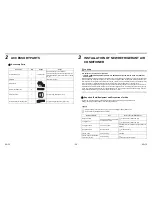
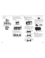
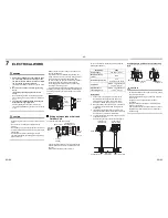
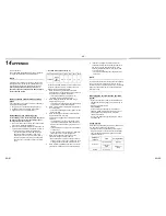
Tightening of Connecting Part
1.
Align the centers of the connecting pipes and fully
tighten the flare nut with your fingers. Then fix the
nut with a wrench as shown in the figure and tighten
it with a torque wrench.
2.
As shown in the figure, be sure to use two wrenches
to loosen or tighten the flare nut of the valve on the
gas side. If you use a single crescent, the flare nut
cannot be tightened to the required tightening
torque.
On the other hand, use a single crescent to loosen
or tighten the flare nut of the valve on the liquid side.
(Unit: N•m)
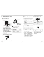
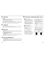
CAUTION
1.
Do not put the crescent wrench on the cap or cover.
The valve may break.
2.
If applying excessive torque, the nut may break
according to some installation conditions.
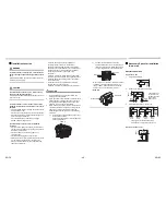
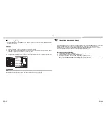
• After the installation work, be sure to check for gas
leaks of the pipe connections with nitrogen.
• Pressure of R410A is higher than that of R22 (Approx.
1.6 times).
Therefore, using a torque wrench, tighten the flare
pipe connecting sections that connect the indoor/
outdoor units at the specified tightening torque.
Incomplete connections may cause not only a gas
leak, but also trouble with the refrigeration cycle.
Outer dia. of copper pipe
Tightening torque
9.5 mm (dia.)
33 to 42 (3.3 to 4.2 kgf•m)
15.9 mm (dia.)
63 to 77 (6.3 to 7.7 kgf•m)
Half union or packed valve
Flare nut
Externally
threaded side
Internally
threaded side
Fix with wrench.
Tighten with torque wrench.
Cover
Piping valve
Tightened
Flare nut
Cap
Loosened
Valve at gas side
Do not apply refrigerant oil to the flared surface.
NO GOOD
Cover
Cap
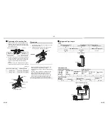
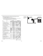
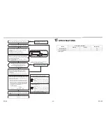
Refrigerant Pipe Length
Single
Simultaneous twin
Allowable pipe length (m)
Height difference (Indoor-outdoor H) (m)
Total length L
Indoor unit: Upper
Outdoor unit: Lower
50
30
30
Pipe diameter (mm)
Number of bent portions
Gas side
Liquid side
10 or less
Ø15.9
Ø9.5
Allowable pipe length (m)
Height difference (m)
Total length
• 1
+ 2
• 1
+ 3
Maximum
Distributed pipes
• 2
• 3
Maximum
Distributed pipes
• 3
– 2
Maximum
Indoor-outdoor H
Indoor-indoor
(
Δ
h)
Indoor unit:
Upper
Outdoor unit:
Upper
50
15
10
30
30
0.5
Pipe diameter (mm)
Number of bent
portions
Main pipe
Branching pipe
Gas side
Liquid side
Gas side
Liquid side
Ø15.9
Ø9.5
Ø12.7
Ø6.4
10 or less
H
L
Figure of Single
Indoor Unit
Outdoor Unit
1
2
3
H
Figure of Simultaneous twin
Indoor Unit
Indoor Unit
Outdoor Unit
Distributor
Summary of Contents for RAV-SP804ATJP-E
Page 54: ... 53 EN 105 EN 106 MEMO ...
Page 55: ... 54 MEMO EN 107 EN 108 ...
Page 56: ...1114550101 ...