background image

– 48 –

9.  CIRCUIT CONFIGURATION AND CONTROL SPECIFICATIONS

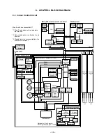
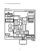
9-1. Microcomputer System Block Diagram

9-1-1. Connection of Main Remote Controller

Main (Sub) master remote controller

Sensor display P.C. board
(MCC-819)

Main P.C. board (MCC-1370A)

Display

LED

CPU

E E P R O M

E E P R O M

TA sensor

TMP47C

820F

Display

LCD

Function setup

Ke y   s w i t c h

Sensors

LED

TA shift setup
Model selection
Function setup

Remote controller 
No. setupTwin/
Triple setup

Sub P.C. board
(MCC-1370B)

#1

#2

B C

Indoor unit

Optional

output

Comp.

Run

Error

Heat

Power

circuit

DC15V

DC

5V

DC

12V

AC

synchronous

signal input

circuit

Serial

send/

receive

circuit

Communication

LSI

Pulse

trans

Indoor fan 

control circuit

Driver

CPU

Serial send/

receive circuit

Serial send/

receive circuit

AC

synchronous

signal input

circuit

TMP87CM

40AN

(TMP87PM

40AN)

TC sensor

TCJ sensor

Louver

motor

Indoor

fan

motor

Transformer

X

Y

Communication P.C. board (Option)

MCC-1337

Outdoor unit

1 2 3
1 2 3

DC310~340V

Power circuit

A B C

A B C

1 2 3

Outdoor

unit

Same as

the left

#3

B C

1 2 3

Outdoor

unit

Same as

the left

Max. 16 units are connectable.

The P.C. boards of the indoor unit are 
classified into 4 boards according to the 
function.
1. Main P.C. board (MCC-1370A)
    Controller for power circuit, fan motor 
    driver, and whole unit
2. Sub P.C. board (MCC-1370B)
    Setup of unit No. and concurrent twin
    * The sub P.C. board is located near the 
    remote controller terminal block.
3. Sensor display P.C. board (MCC-819)
    Wireless remote controller receive part, 
    LED display part
4. Communication P.C. board (MCC-1337)
    Communication part with the central 
    control remote controller (Option)

Summary of Contents for RAV-SM560AT-E

Page 1: ...M800UT E RAV SM560BT E RAV SM800BT E RAV SM560KRT E RAV SM800KRT E RAV SM560XT E RAV SM800XT E PRINTED IN JAPAN Apr 2003 ToMo File No A02 014 in the page of the following table has been changed and the portion is expressed as mark 2 3 5 11 20 21 29 57 Revised page 59 60 63 64 168 170 Cord Heater Installation Work ...

Page 2: ...LECTRICAL PARTS 28 7 REFRIGERANT R410A 30 8 CONTROL BLOCK DIAGRAM 38 9 CIRCUIT CONFIGURATION AND CONTROL SPECIFICATIONS 48 10 TROUBLESHOOTING 65 11 REPLACEMENT OF SERVICE INDOOR P C BOARD 88 12 SETUP AT LOCAL SITE AND OTHERS 92 13 ADDRESS SETUP 103 14 TROUBLESHOOTING WALL TYPE 108 15 DETACHMENTS 135 16 EXPLODED VIEWS AND PARTS LIST 168 CORD HEATER INSTALLATION WORK APPENDIX 1 ...

Page 3: ...ption kW characteristics Low temp kW Power factor Main unit Appearance Ceiling Panel Model Sold separately Panel color Height mm Main unit Width mm Outer Depth mm dimension Ceiling panel Height mm Width mm Sold separately Depth mm Total weight Main unit kg Ceiling panel Heat exchanger Soundproof Heat insulating material Fan Fan unit Standard air flow High Mid Low m h Motor W Air filter Controller ...

Page 4: ...40 60 80 90 100 2 4 6 8 10 12 16 14 Compressor speed rps Current A RAV SM800UT E RAV SM560UT E Conditions Indoor DB20 C Outdoor DB7 C WB6 C Air flow High Pipe length 7 5m 230V 50 55 60 65 70 75 80 85 90 95 100 105 32 33 34 35 36 37 38 39 40 41 42 43 Outsoor temp C Capacity ratio Conditions Indoor DB27 C WB19 C Indoor air flow High Pipe length 7 5m 0 10 20 30 40 50 60 70 80 90 100 110 120 14 12 10 ...

Page 5: ...umption kW characteristics Low temp kW Power factor Main unit Appearance Ceiling Panel Model Sold separately Panel color Height mm Main unit Width mm Outer Depth mm dimension Ceiling panel Height mm Width mm Sold separately Depth mm Total weight Main unit kg Ceiling panel Heat exchanger Soundproof Heat insulating material Fan Fan unit Standard air flow High Mid Low m h Motor W Air filter Controlle...

Page 6: ...0 2 4 6 8 10 12 16 14 Compressor speed rps Current A RAV SM560BT E Conditions Indoor DB20 C Outdoor DB7 C WB6 C Air flow High Pipe length 7 5m 230V 50 55 60 65 70 75 80 85 90 95 100 105 32 33 34 35 36 37 38 39 40 41 42 43 Outsoor temp C Capacity ratio Conditions Indoor DB27 C WB19 C Indoor air flow High Pipe length 7 5m RAV SM800BT E RAV SM800BT E 0 10 20 30 40 50 60 70 80 90 100 110 120 14 12 10 ...

Page 7: ...onsumption kW characteristics Low temp kW Power factor Main unit Appearance Ceiling Panel Model Sold separately Panel color Height mm Main unit Width mm Outer Depth mm dimension Ceiling panel Height mm Width mm Sold separately Depth mm Total weight Main unit kg Ceiling panel Heat exchanger Soundproof Heat insulating material Fan Fan unit Standard air flow High Mid Low m h Motor W Air filter Contro...

Page 8: ... 2 4 6 8 10 12 16 14 Compressor speed rps Current A RAV SM800KRT E RAV SM560KRT E Conditions Indoor DB20 C Outdoor DB7 C WB6 C Air flow High Pipe length 7 5m 230V 50 55 60 65 70 75 80 85 90 95 100 105 32 33 34 35 36 37 38 39 40 41 42 43 Outsoor temp C Capacity ratio Conditions Indoor DB27 C WB19 C Indoor air flow High Pipe length 7 5m RAV SM800KRT E 0 10 20 30 40 50 60 70 80 90 100 110 120 14 12 1...

Page 9: ...sumption kW characteristics Low temp kW Power factor Main unit Appearance Ceiling Panel Model Sold separately Panel color Height mm Main unit Width mm Outer Depth mm dimension Ceiling panel Height mm Width mm Sold separately Depth mm Total weight Main unit kg Ceiling panel Heat exchanger Soundproof Heat insulating material Fan Fan unit Standard air flow High Mid Low m h Motor W Air filter Controll...

Page 10: ...100 2 4 6 8 10 12 14 Compressor speed rps Current A RAV SM800XT E RAV SM560XT E Conditions Indoor DB20 C Outdoor DB7 C WB6 C Air flow High Pipe length 7 5m 230V 50 55 60 65 70 75 80 85 90 95 100 105 32 33 34 35 36 37 38 39 40 41 42 43 Outsoor temp C Capacity ratio Conditions Indoor DB27 C WB19 C Indoor air flow High Pipe length 7 5m 0 10 20 30 40 50 60 70 80 90 100 110 120 14 12 10 8 6 4 2 0 2 4 6...

Page 11: ...r supply Type Compressor Motor kW Pole Refrigerant charged kg Refrigerant control Standard length Max total length m Pipe Over 20m Height difference Outdoor lower m Outdoor higher m Outer Height mm Width mm dimension Depth mm Total weight kg Heat exchanger Fan Fan unit Standard air flow High m h Motor W Connecting Gas side mm pipe Liquid side mm Protection device Sound level High Mid Low dB A Note...

Page 12: ... 42 39 36 44 41 38 Indoor Unit Outdoor Unit Standard capacity Note 1 kW Energy consumption effect ratio Power supply Electrical Running current A characteristics Power kW consumption Power factor Sound level High Mid Low Indoor unit Note 2 dB A RAV SM561CT E RAV SM801CT E RAV SM1101CT E RAV SM1401CT E RAV SP560AT E RAV SP800AT E RAV SP1100AT E RAV SP1400AT E Cooling Heating Cooling Heating Cooling...

Page 13: ...c pressure mmAq Standard air volume 840m h Standard air volume 1140m h Air volume m hr Air volume m hr 500 1000 700 1300 High tap Extra High tap Low tap Low tap High tap Extra High tap Low tap High tap Extra High tap Middole tap Low tap High tap Extra High tap Middole tap Middle tap Middle tap 2 AIR DUCTING WORK 2 1 Static Pressure Characteristics of Each Model Fig 1 RAV SM560BT E Fig 2 RAV SM800B...

Page 14: ...ing Surface under ceiling Surface under ceiling Surface under ceiling Standing 850 or less Standing 640 or less Surface under ceiling 840 Hanging bolt Z view Drain up standing size Ceiling panel Sold separately Knockout for humidifier 723 Hanging bolt pitch 950 Panel external dimension 840 Unit external dimension 790 Hanging bolt pitch 950 Panel external dimension Electric parts box Refrigerant pi...

Page 15: ...hloride pipe Inner dia 32 Nominal dia 25 Refrigerant pipe connecting port Liquid side Ø6 4 Ø125 knockout hole Only rear side For air suction 6 Ø4 tapping screw lower hole Ø160 Suction port canvas Suction panel 470 Ceiling opening size Panel 2 Ø26 power supply remote controller cord draw out port Drain pipe connecting port at main unit side For polyvinyl chloride pipe Inner dia 32 Nominal dia 25 Pl...

Page 16: ...e pipe Inner dia 32 Nominal dia 25 Refrigerant pipe connecting port Liquid side Ø6 4 Ø125 knockout hole Only rear side For air suction 6 Ø4 tapping screw lower hole Ø160 Suction port canvas Suction panel 470 Ceiling opening size Panel 2 Ø26 power supply remote controller cord draw out port Drain pipe connecting port at main unit side For polyvinyl chloride pipe Inner dia 32 Nominal dia 25 Plane vi...

Page 17: ...50 Pipe port from lower side Knockout hole 75 56 Drain hose Z views Refrigerant pipe connecting port B Refrigerant pipe connecting port A 110 390 490 540 998 763 5 450 20 10 29 48 48 40 40 41 55 55 55 298 20 100 100 115 115 Position of installation plate 53 or more 53 or more 55 or more Space required for service SM560 SM800 Ø9 5 Ø6 4 A Liquid Side Ø15 9 Ø12 7 B Gas Side ...

Page 18: ...system For stud bolt Ø8 Ø10 For stud bolt Ø6 Grille air inlet Back body Installation plate Mount plate M10 Suspention bolt Wireless remote control Knock out system 200 Min 1093 1015 742 450 20 20 330 165 Ø 7 4 70 Min 633 460 57 18 160 633 208 1093 UNDER CEILING CONSOLE INSTALLATION ...

Page 19: ... 147 500 Fan center dividing 90 6 132 598 593 521 21 49 3 Discharge guard Discharge guide mounting hole 4 Ø4 embossing 500 Fan center dividing Protective net mounting hole 2 Ø4 embossing 21 216 Charge port Earth terminal Valve cover 365 600 2 Ø11 x 14 U shape holes For Ø8 Ø10 anchor bolt Suction port Discharge port Discharge port Minimum distance up to wall 2 Ø11 x 14 long hole For Ø8 Ø10 anchor b...

Page 20: ...d side Refrigerant pipe connecting port Ø15 9 flare at gas side Discharge guide mounting hole 4 Ø4 embossing 1 1 2 2 795 85 165 60 80 25 60 90 320 28 400 161 58 46 30 45 27 Space required for service 365 600 2 Ø12 x 17 U shape holes For Ø8 Ø10 anchor bolt Suction port Discharge port Discharge port Minimum distance up to wall 2 Ø12 x 17 long hole For Ø8 Ø10 anchor bolt 500 or more 150 or more 150 o...

Page 21: ...0 93 20 15 57 20 7 3 5 71 1 39 3 78 20 54 19 110 20 26 22 Compressor revolutions per second rps 74 72 28 84 47 110 Indoor fan HIGH HIGH LOW HIGH LOW HIGH Indoor Outdoor temp conditions DB WB C Indoor Outdoor 27 19 35 32 24 43 18 15 5 5 20 7 6 30 24 18 15 20 70 Indoor unit Outdoor unit Outer diameter of refrigerant pipe Gas side ØA Liquid side ØB 12 7mm 6 4mm TCJ sensor Air heat exchanger Strainer ...

Page 22: ... 16 89 16 34 18 Compressor revolutions per second rps 64 52 27 65 31 90 Indoor fan HIGH HIGH LOW HIGH LOW HIGH Indoor Outdoor temp conditions DB WB C Indoor Outdoor 27 19 35 32 24 43 18 15 5 5 20 7 6 30 24 18 15 20 70 Indoor unit Outdoor unit Outer diameter of refrigerant pipe Gas side ØA Liquid side ØB 15 9mm 9 5mm TCJ sensor Air heat exchanger Strainer Strainer TC sensor Refrigerant pipe at liqu...

Page 23: ... 4 5 5 5 5 4 4 3 3 2 2 1 1 1 1 2 2 3 3 4 4 5 5 1 1 2 2 3 3 4 4 5 5 LM2 FM LM1 Motor drive circuit Motor drive circuit Power supply circuit DC20V DC15V DC12V DC7V Fuse F302 T3 15A 250V 1 2 1 2 3 3 1 2 1 2 3 3 1 2 3 4 4 5 5 DP CN333 WHI CN334 WHI CN68 BLU CN304 GRY 1 2 CN66 WHI CN41 BLU CN309 YEL CN50 WHI CN60 WHI 1 2 CN32 WHI 1 2 3 4 5 6 1 2 3 4 5 CN620 BLU 1 2 3 4 5 6 CN61 YEL CN67 BLK RED WHI BLK...

Page 24: ... 3 4 5 6 7 1 2 3 4 5 6 7 1 2 3 4 5 6 7 8 9 1 2 3 4 5 6 7 8 9 1 2 3 4 5 6 7 8 9 1 2 3 4 5 6 7 1 2 3 4 5 6 7 1 2 3 4 5 6 7 8 9 1 2 3 4 5 6 7 8 9 2 3 CN304 GRY RY 004 RED YEL BLU ORN BLK UL L M H RED WHI WHI BLK 3 2 1 3 2 1 N L Indoor unit earth screw Outdoor unit earth screw RED Closed end connector Fuse F001 T5A 250V RY001 RY002 RY006 RY007 RY005 When selecting high static pressure Color Identifica...

Page 25: ...LU BLU BLU BLU BLU BLU BLU BLU 1 1 2 2 GRY PNK FM LM BLU YEL WHI BLK RED 1 1 2 2 3 3 4 4 5 5 6 6 BLU PNK YEL OPG RED BRN 1 1 2 2 1 RED GRN YEL CN230 Earth Screw Power Supply 220 240 50Hz Serial Signal 2 WHI CN231 3 BLK CN223 1 2 3 L N F2 Outdoor unit 1 Phase model Indoor unit F201 T3 15A 250V Infra Red Receiver 1 1 1 1 2 2 2 2 3 3 4 4 5 5 6 6 1 1 1 1 2 2 2 2 3 3 4 4 5 5 6 6 1 1 2 2 3 3 CN62 WHI CN...

Page 26: ...indicator Terminal block Fuse 6 3A DC 5V DC 12V 1 2 3 4 5 1 2 2 1 3 4 5 6 7 8 9 10 1 2 3 4 5 6 7 8 9 10 1 2 3 4 5 6 7 8 9 10 1 2 3 4 5 6 7 8 9 10 INFRARED RAYS RECEIVE AND INDICATION PARTS SWITCH PCB MCC 1428B BRW RED ORN YEL PNK BLU BLU WHI BLU BLU BLU BLU BLU BLU BLU BLU CN13 CN07 CN100 CN402 J401 C01 R01 DB01 C02 DC12V IC03 C501 R405 R21 R22 SG01 F01 T6 3A FUSE 250VAC R09 R507 CR401 RY401 R506 ...

Page 27: ...emp Sensor Outdoor Temp Sensor Suction Temp Sensor Insulated Gate Bipolar Transistor Converter module Curreut Transformer Fan motor driver module NOTE Color Identification BLK BLU RED GRY PNK GRN BLACK BLUE RED GRAY PINK GREEN WHI BRW ORN YEL PUR WHITE BROWN ORANGE YELLOW PURPLE P10 ORN BRW BZ BY BX EW BW EV BV EU BU BLU P09 P19 P20 CT C12 C13 C14 REACTOR THERMOSTAT FOR COMPRESSOR P08 P07 CN500 CN...

Page 28: ...LLOW PURPLE 3 2 1 3 2 1 2 1 2 1 5 4 1 5 4 3 2 3 2 1 3 1 3 1 6 5 4 3 2 1 6 5 4 3 2 1 ORN ORN VARISTOR T02 CT G E A DB01 Converter module SURGE ABSORBER PHOTO COUPLER P C BOARD MCC 1359 SUB P C BOARD MCC 1398 F01 FUSE T3 15A F01 FUSE 25A CN01 CN02 P12 P09 P11 P13 P19 P18 P17 P20 P10 RY01 R05 R06 CN04 CN800 CN302 CN06 CN05 CN04 C13 CN03 CN02 CN01 CN702 THERMOSTAT FOR COMPRESSOR CN500 CN700 CN300 CN30...

Page 29: ... 10 kΩ at 25 C 10 kΩ at 25 C 10 kΩ at 25 C Parts name Fan motor RAV SM800BT E Fan motor RAV SM560BT E Capacitor RAV SM800BT E Capacitor RAV SM560BT E Thermo sensor TA sensor Heat exchanger sensor TC sensor Heat exchanger sensor TCJ sensor Type STF 230 80 4C STF 220 80 4C EAG40M805UF1 CMPS400 4 0 818 mm Ø6 mm 1200 mm Ø6 mm 1200 mm No 1 2 3 4 5 Specifications Output Rated 30 W 220 240 V 10 kΩ at 25 ...

Page 30: ...enoid coil Compressor thermo Protection Type ICF 140 43 1 DA130A1F 23F CH 57 STF 0108G US 622 No 1 2 3 4 5 6 7 8 9 10 11 Specifications Output Rated 63 W 220 240 V 3 phase 4P 1600 W 8 mH 16 A 10 kΩ at 25 C 10 kΩ at 25 C 10 kΩ at 25 C 50 kΩ at 25 C T3 15 A AC 250 V 25 A AC 250 V ON 90 5 C OFF 125 4 C Parts name Fan motor Compressor Reactor Outdoor temp sensor To sensor Heat exchanger sensor Te sens...

Page 31: ...e pressure in the refrigeration cycle may become abnormally high so that a rupture or personal injury may be caused 5 After completion of installation work check to make sure that there is no refrigeration gas leakage If the refrigerant gas leaks into the room coming into contact with fire in the fan driven heater space heater etc a poisonous gas may occur 6 When an air conditioning system charged...

Page 32: ...nections and used mainly for thick pipings whose diameter is larger than 20 mm Thicknesses of socket joints are as shown in Table 7 2 2 Table 7 2 2 Minimum thicknesses of socket joints 7 2 2 Processing of Piping Materials When performing the refrigerant piping installation care should be taken to ensure that water or dust does not enter the pipe interior that no other oil other than lubricating oi...

Page 33: ...nal diameter 1 4 3 8 1 2 5 8 Dimension mm A B C D 9 1 9 2 6 5 13 13 2 13 5 9 7 20 16 6 16 0 12 9 23 19 7 19 0 16 0 25 Outer diameter mm 6 35 9 52 12 70 15 88 Thickness mm 0 8 0 8 0 8 1 0 Flare nut width mm 17 22 26 29 c Insertion of Flare Nut d Flare Processing Make certain that a clamp bar and copper pipe have been cleaned By means of the clamp bar perform the flare processing correctly Use eithe...

Page 34: ...nd flare seal surface 2 Flare Connecting Procedures and Precautions a Make sure that the flare and union portions do not have any scar or dust etc b Correctly align the processed flare surface with the union axis c Tighten the flare with designated torque by means of a torque wrench The tightening torque for R410A is the same as that for conventional R22 Incidentally when the torque is weak the ga...

Page 35: ...f sludge clogging of capillary etc Accordingly the tools to be used are classified into the following three types 1 Tools exclusive for R410A Those which cannot be used for conventional refrigerant R22 2 Tools exclusive for R410A but can be also used for conventional refrigerant R22 3 Tools commonly used for R410A and for conventional refrigerant R22 The table below shows the tools exclusive for R...

Page 36: ...p the status as it is for 1 to 2 minutes and ensure that the compound gauge s pointer does not return Set the refrigerant cylinder to the electronic balance connect the connecting hose to the cylinder and the connecting port of the electronic balance and charge liquid refrigerant 7 4 Recharging of Refrigerant When it is necessary to recharge refrigerant charge the specified amount of new refrigera...

Page 37: ...oy mainly composed of silver and copper It is used to join iron copper or copper alloy and is relatively expen sive though it excels in solderability 2 Phosphor bronze brazing filler Phosphor bronze brazing filler is generally used to join copper or copper alloy 3 Low temperature brazing filler Low temperature brazing filler is generally called solder and is an alloy of tin and lead Since it is we...

Page 38: ...er flux Do not enter flux into the refrigeration cycle When chlorine contained in the flux remains within the pipe the lubricating oil deteriorates Therefore use a flux which does not contain chlorine When adding water to the flux use water which does not contain chlorine e g distilled water or ion exchange water Remove the flux after brazing 7 5 3 Brazing As brazing work requires sophisticated te...

Page 39: ... circuit DC5V CPU LCD driver Display LCD Function setup Key switch Weekly timer Secondary battery DC5V DC5V 3 CN2 CN1 A B 1 2 3 Outdoor unit Same as the left 2 2 A B 1 2 3 Outdoor unit Same as the left 2 Max 8 units are connectable 1 1 Max 7 units when network adapters are attached 2 Network adapters are attached to only one unit 3 Weekly timer is not connectable to the sub remote controller Netwo...

Page 40: ...ing operation Dry operation Heating operation COOL HEAT operation mode is automatically selected by Ta and Ts for operation 1 Judge the selection of COOL HEAT mode as shown in the figure above When 10 minutes passed after thermostat had been turned off the heating operation Thermo OFF is exchanged to cooling operation if Tsh exceeds 1 5 or more COOL OFF and COOL ON in the figure indicate an exampl...

Page 41: ... AUTO mode is performed by the command from the remote controller 2 When the air speed mode AUTO is selected the air speed varies by the difference between Ta and Ts COOL HH H L LL Air speed selection 4 5 Shift of suction tempera ture in heating operation Controlling operation in case when thermo of remote controller works is same as a case when thermo of the body works If the air speed has been c...

Page 42: ...r temperature Standard COOL HEAT UL UL L L L L M M M M H H High ceiling COOL HEAT UL UL L L L L M M M M H H Tap FD FD FB FA F9 F8 F7 F6 F5 F4 F3 F2 F1 SM560 SM800 Revolutions per minute rpm 320 320 320 330 330 340 350 360 360 370 370 380 400 410 410 440 420 450 440 480 480 500 530 540 580 580 3 In heating operation the mode changes to UL if thermostat is turned off 4 If Ta 25 C when heating operat...

Page 43: ...d frequency becomes S0 because the operation continues in J zone the return temperature A is raised from 5 C to 12 C until I zone is detected and the indoor fan operates with M mode In heating operation the freeze preventive control works if 4 way valve is not exchanged and the condition is satisfied However the temperature for J zone dashing control is changed from 2 C to 5 C 7 8 Freeze preven ti...

Page 44: ...ll modes In group twin triple operation the swinging positions can be set up collectively or individu ally 3 When the unit stops or when a warning is output the flap automatically moves downward 4 While the heating operation is ready the flap automatically moves upward 1 Flap position setup When the flap position is changed the position moves necessarily to downward discharge position once to retu...

Page 45: ... P C board switch S003 from OFF to ON Attach the sensor P C board cover and mount the adjuster with sensors to the ceiling panel Turn on the power of the set 3 Push ON OFF button of the wireless remote controller and set the operation mode to COOL or HEAT using MODE button During test run operation all the display lamps of wireless remote controller sensors flash Do not use other mode than COOL HE...

Page 46: ...d corrected in the range not to lose the comfort ability according to input values of various sensors 3 Data Input value room temp Ta Outside temp To Air volume Indoor heat exchanger sensor temp Tc for 20 minutes are taken the average to calculate correction value of the setup temperature 4 The setup temperature is shifted every 20 minutes and the shifted range is as follows In cooling time 1 5 to...

Page 47: ...02 Microcomputer operation LED EEPROM Network adapter power supply Indoor Outdoor inter unit cable Remote controller power LED Drain pump output Remote controller inter unit cable EXCT Outside error input TC sensor TCJ sensor DISP CHK TA sensor Optional output Louver Float SW DC fan return DC fan output ...

Page 48: ...ansformer input AC11V 14V 20V Microcomputer operation LED Power transformer output Louver Drain pump output Network adapter power supply Fan output TA sensor EXCT Float SW Outside error input TCJ sensor TCsensor CHK Remote controller inter unit cable DISP Optional output HA Remote controller power LED ...

Page 49: ...ive circuit Serial send receive circuit AC synchronous signal input circuit TMP87CM 40AN TMP87PM 40AN TC sensor TCJ sensor Louver motor Indoor fan motor Transformer X Y Communication P C board Option MCC 1337 Outdoor unit 1 2 3 1 2 3 DC310 340V Power circuit A B C A B C 1 2 3 Outdoor unit Same as the left 3 B C 1 2 3 Outdoor unit Same as the left Max 16 units are connectable The P C boards of the ...

Page 50: ...ndoor unit Optional output Comp Run Error Heat Power circuit DC15V DC 5V 1 2 3 1 2 3 DC 12V AC synchronous signal input circuit Serial send receive circuit Communication LSI Pulse trans Indoor fan control circuit Driver CPU TMP87CM 40AN TMP87PM 40AN TC sensor TCJ sensor Louver motor Indoor fan motor Transformer X Y Communication P C board Option MCC 1337 Outdoor unit DC310 340V Infrared radiation ...

Page 51: ...g operation Thermo OFF is exchanged to heating operation if Tsc exceeds 3 or less 2 For the automatic capacity control after judgment of COOL HEAT refer to item 4 3 For the temperature correction of room temperature control in automatic heating operation refer to item 3 Ta Room temperature Ts Setup temperature Tsc Setup temperature in cooling operation Tsh Setup temperature in heating operation 1 ...

Page 52: ...the rated heating frequency 1 2 3 4 5 Ta 19 C Indoor fan High 5 C To 10 C or no To Operation exceeding the rated heating frequency Tc 38 C NOTE When air volume is set to L the maximum frequency is restricted Tc Temperature of indoor heat exchanger sensor 1 Operation with HIGH H MED M LOW L or AUTO mode is performed by the command from the remote controller 2 When the air volume mode AUTO is select...

Page 53: ... HIGH H is set larger than that in the standard cooling heating operation However the revolution frequency is restricted in the automatic heating operation as shown in the following figure Stop is a cool air discharge preventive control operation by Tc Tc Indoor heat exchanger sensor temp Display AUTO 6 For wireless type only The mode enters AUTO in automatic cooling heating operation 7 The mode e...

Page 54: ...e return temperature A is raised from 5 C to 12 C until I zone is detected and the indoor fan operates with L mode In heating operation the freeze preventive control works if 4 way valve is not exchanged and the condition is satisfied High temp release control 1 The heating operation is performed as follows based on the detected temperature of Tc sensor When M zone is detected the commanded freque...

Page 55: ...ller continuously for 5 seconds the mode enters TEST The indoor fan rotates with HIGH and a frequency fixed operation starts 2 During this operation the buttons other than ON OFF UP and DOWN cannot be accepted However items 7 and 8 are effective 3 To stop the frequency fixed operation use ON OFF button only 2 In case of wireless remote controller Without wired remote controller 1 When pushing Temp...

Page 56: ...push priority The operation contents can be selected from both remote controller and the central controller of the indoor unit side and the operation is performed with the contents selected at the last Center Start Stop operation only can be handled on the remote controller at indoor unit side Operation Prohibited It cannot be operated on the remote controller at indoor unit side Stop status is he...

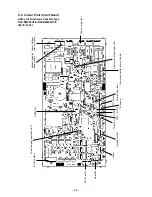
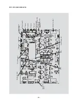
Page 57: ... 56 9 2 Indoor Control Circuit 9 2 1 Print Circuit Board Main P C board MCC 1370A Sub P C board MCC 1370B ...

Page 58: ...ls the operation frequency that is lowers the operation frequency when the discharge temperature has not lower or the discharge temperature has rapidly risen during PMV control It subdivides the fre quency control up to a unit of 0 6Hz to stabi lize the cycle 2 When the discharge temperature is detected in an abnormal stop zone the unit stops the compressor and restarts after 2 minutes 30 seconds ...

Page 59: ... operation mode is in cooling system COOL DRY COOL in AUTO cooling heating ON when operation mode is in heating system HEAT HEAT in AUTO cooling heating ON during indoor fan ON Air purifier is used Interlock cable When continued for 1 minute Check code L30 is output and forced operation stops Option error input is controlled Protective operation for device attached to outside is displayed Setting ...

Page 60: ...om parts of P C board MCC 813 RAV SM560AT E 5V power supply MCU GND 12V power supply PMV output TD sensor TS sensor TO sensor TE sensor Outdoor fan rpm input Case thermo Outdoor fan output IGB module Converter module 4 way valve output Except cooling only models ...

Page 61: ...utput 12V power supply PMV output Case thermo Contactor against night low noise 5V power supply TD sensor TO sensor TE sensor Communication between CDB and IPDU TS sensor Outdoor fan output Status display LED MCU GND Existing pipe corresponding switch SW 801 ...

Page 62: ...uring defrost operation Control for fan tap by outdoor temperature in normal operation 1 Cooling fan control Q The outdoor fan is controlled by TE sensor Cooling Temperature conditions after medium term The cooling fan is controlled by every 1 tap of DC fan control 14 taps R At the activation time although the maximum fan tap in the following table are fixed for 60 seconds after then the fan may n...

Page 63: ... be caused As same as a test run it is recommended to turn on power of the compressor beforehand when starting operation after power of the compressor has been interrupted for a long time 3 A judgment for electricity is performed by TD and TO sensors If TO sensor is defective a backup control is automatically performed by TE sensor For a case of defective TO sensor judge it with the outdoor LED di...

Page 64: ...formed Error code P04 is displayed V After restarting the compressor continue controlling by using 70 to 90 of the control value of the current release control for minimum 30 minutes 6 Over current preventive control Q This control function stops the compressor when over current preventive circuit has detected an abnormal current R The compressor restarts with error count 1 after 2 minutes 30 seco...

Page 65: ...the compressor and the outdoor fan start heating operation after stopped for approx 50 seconds Start of heating operation a b c d T SM560 28 28 28 60 120 A zone B zone C zone D zone Defrost operation is performed in this zone when TE0 TE 3 continued for T seconds Defrost operation is performed in this zone when TE0 TE 3 continued for T seconds Defrost operation is performed when this zone continue...

Page 66: ...es not outside low temperature operation control work in cooling operation Is not defrost operation performed d ON OFF operation cannot be performed from remote controller Is not the control operation performed from outside remote side Is not automatic address being set up When the power is turned on at the first time or when indoor unit address setting is changed the operation cannot be performed...

Page 67: ...r Is not forced operation performed Is not the control operation performed from outside remote side Is not automatic address being set up Q Did you return the cabling to the initial positions R Are connecting cables between indoor unit and receiving unit correct 2 Troubleshooting procedure When the power is turned on at the first time or when indoor unit address setting is changed the operation ca...

Page 68: ...error is detected Displayed when error is detected Displayed when error is detected Displayed when error is detected Displayed when error is detected Displayed when error is detected Displayed when error is detected Displayed when error is detected Displayed when error is detected Displayed when error is detected Displayed when error is detected Displayed when error is detected Judgment and measur...

Page 69: ...ayed when error is detected Displayed when error is detected Displayed when error is detected Displayed when error is detected Displayed when error is detected Displayed when error is detected Displayed when error is detected Displayed when error is detected Displayed when error is detected Judgment and measures 1 Check power voltage AC200V 20V 2 Overload operation of refrigerating cycle 3 Check c...

Page 70: ...ayed when error is detected Displayed when error is detected Displayed when error is detected Displayed when error is detected Displayed when error is detected Displayed when error is detected Judgment and measures Remote controller power error Defective indoor EEPROM 1 Check remote controller inter unit cables 2 Check remote controller 3 Check indoor power cables 4 Check indoor P C board 5 Check ...

Page 71: ... error Discharge temp error DC outdoor fan error Communication error between IPDU Abnormal stop High pressure release operation EEPROM error Communication error between IPDU No abnormal stop G Tr short circuit protection Detection circuit error Current sensor error Phase missing detection Comp lock error Comp breakdown Check code Type A Type B F06 18 F04 19 F06 18 F08 1B P03 1E P22 1A L29 1C P04 2...

Page 72: ...indoor units turned on Is power supplied to remote controller AB terminal Approx DC18V Are two remote controllers set without master unit Are two remote controllers set without master unit Correct inter unit cable of remote controller Correct connection of connector Check circuit cables Check power connection of indoor unit Turn on power again Check indoor P C board MCC 1402 Defect Replace Correct...

Page 73: ...500 connected Does case thermo operate Are 1 2 3 inter unit cables normal Are connections from connectors of inter terminal blocks 1 2 3 of indoor outdoor units normal Does voltage between 2 and 3 of inter terminal blocks 1 2 3 of indoor unit vary Is DC280V applied between terminals of electrolytic capacitor of IPDU main circuit Check indoor P C board MCC 1402 Defect Replace As shown in the follow...

Page 74: ...dress setup mode Check code is not displayed However if the above is detected during automatic address setup mode the check code may be displayed L09 error 46 error Is inter unit cable of A and B normal Is there no disconnection or contact error of connector on harness from terminal block of indoor unit Is group control operation Is power of all indoor units turned on Correct inter unit cable of r...

Page 75: ...ntral controller including network adapter Defect Replace NO NO YES NO NO NO NO YES YES YES NO YES YES YES YES Are cable connections to communication line X Y normal Is indoor remote controller L20 displayed Is central controller 98 displayed Are outside devices of connector CN80 connected Is check code displayed on sub unit of main or sub remote controller Do outside devices normally operate Is g...

Page 76: ...t Replace Check indoor P C board MCC 1402 or MCC 1403 Defect Replace Replace drain pump Check cabling Refer to Characteristics 1 NO NO NO NO NO YES YES YES YES YES Does float switch operate Does drain pump operate Is circuit cabling normal Is power of drain pump turned on Is connection of float switch connector Indoor control P C board CH34 normal NO YES Is connection of TA sensor connector indoor...

Page 77: ...indoor P C board MCC 1402 under condition that CN333 and CN334 are mounted and the power is turned on Rotate the fan slowly with hands and check the pin voltage swings between 0 to 5V voltage Between and 5V Check indoor P C board MCC 1402 Defect Replace Remove connectors CN333 and CN334 of indoor unit P C board MCC 1402 Replace indoor fan motor Replace indoor fan motor Replace indoor fan motor YES...

Page 78: ... and Red lead of motor winding of connector CN301 The status that there is 5k to 20k resistance values between Yellow lead and Pink lead of motor position detection of connector CN300 is normal Normal fan motor Control or CDB P C board Defective fan motor NOTE However GND circuit error inside of the motor is rarely detected even if the above check is carried out When the circuit does not become no...

Page 79: ...ce electron expansion valve Check indoor P C board Defect Replace Replace TC sensor Is operation of 4 way valve normal Is voltage applied to 4 way valve coil terminal in heating operation Is circuit cable normal Check CDB P C board Is flow of refrigerant by electron expansion valve normal Are characteristics of TC sensor resistance value normal Check and correct circuit Correct connection of conne...

Page 80: ...check RY01 on the control P C board Single phase type is not provided to RAV SM560AT E Replace control P C board of RAV SM560AT E Is power voltage normal Is not AC fuse fused Check and correct circuit cables Correct connection of connector Check and correct reactor connection Are connections of cabling connector normal Does RY01 relay of IPDU operate Are not P26 and 14 errors output when an operat...

Page 81: ...ing shorted Is resistance between windings 0 6 to 1 2 Is compressor normal Is not earthed Is not winding opened Compressor error Replace Compressor error Replace Compressor error Replace Check and correct circuit cables Check and correct circuit cabling such as cabling to compressor Check IPDU P C board Defect Replace Check IPDU Defect Replace For RAV SM560AT E replace control P C board YES YES NO...

Page 82: ...Are characteristics of TD sensor resistance value normal Replace TD sensor YES NO Is connection of TO sensor connector of CDB CN601 normal Correct connection of connector Check CDB Defect Replace Refer to Characteristics 5 For RAV SM560AT E CN602 TO sensor YES NO Are characteristics of TO sensor resistance value normal Replace TO sensor YES For RAV SM560AT E CN600 TE sensor and CN603 TS sensor For...

Page 83: ...prove power line Compressor lock Replace Check cabling between IPDU and CDB and connector IPDU P C board error Defect Replace IPDU P C board error Defect Replace Check TE and TS sensors Replace Check electron expansion valve Replace Is there no slackened refrigerant Does electron expansion valve normally operate Is power voltage normal Is compressor normal Are connections of cable connector normal...

Page 84: ...elease control normal Are connections of cable connector normal Correct the cabling and connection of connector Improve and delete the cause Replace TD sensor Improve power line Improve and delete the cause Check and correct circuit cables Check CDB Defect Replace Check and correct the charged refrigerant amount For RAV SM560AT E replace control P C board Check IPDU Defect Replace For RAV SM560AT ...

Page 85: ...ling connector Check TE sensor Defect Replace Correct connection of connector Check TE TC TS sensors Replace electron expansion valve Replace TD TO and TC sensors Check CDB Defect Replace Does cooling outdoor fan normally operate Does PMV normally operate Is fan motor normal Replace fan motor Correct coming off Are characteristics of TD TO TC sensor resistance values normal Check charged refrigera...

Page 86: ...dapter P C board and connectors CN309 CN41 of indoor P C board MCC 1402 or MCC 1403 normal Check connections of A B terminal blocks Correct communication line of remote controller Check central controller Defect Replace Check indoor P C board MCC 1402 or MCC 1403 Defect Replace Check network adapter P C board and power transformer Defect Replace Is the network address changed form remote controlle...

Page 87: ...the indoor unit P C board during operation of the air conditioner Replace the service P C board If EEPROM has not been inserted when the power was turned on or if EEPROM data never be read written the automatic address mode is repeated In this time the central controller displays 97 error Power ON SET is displayed on main remote controller SET goes off LED D02 on indoor unit P C board flashes with...

Page 88: ...emperature C Temperature C Resistance k 10 C or lower Resistance k 50 C or lower Temperature C Resistance k 50 C or higher Resistance k 10 C or higher Caracteristics 4 Temperature C TC TCJ sensor TE TO TS sensor TD sensor TA sensor 20 10 0 10 20 40 30 50 200 100 20 10 0 0 10 0 10 20 40 30 50 60 70 40 30 20 10 0 0 10 10 30 20 40 50 60 70 200 100 20 10 0 0 50 100 ...

Page 89: ...ding to the following procedure After replacement check the indoor unit address and also the cycle by a test run REPLACEMENT PROCEDURE CASE 1 Before replacement power of the indoor unit can be turned on and the setup data can be readout from the wired remote controller Read EEPROM data 1 ref P89 ò Replace service P C board power ON 2 ref P89 ò Write the read data to EEPROM 3 ref P90 ò Power reset ...

Page 90: ...de and a manual resetting may be required r2 Replacement of service P C board 1 Replace the P C board with a service P C board In this time setting of jumper line cut or setting of short circuit connecting connectors on the former P C board should be reflected on the service P C board 2 According to the system configuration turn on power of the indoor unit with any method in the following items a ...

Page 91: ...de DN 5 Using the timer time buttons set the capacity For example 0012 for class 80 Refer to the attached table 6 Push SET button OK when the display goes on 7 Push button to return the status to usual stop status 6 Approx 1 minute is required to start handling of the remote controller 5 Next write the contents which have been set up at the local site such as the address setup in EEPROM Repeat the...

Page 92: ...set Wired remote controller Correction of high heat feeling Memo At shipment According to type 0000 Standard 0099 Unfixed 0002 2 C Floor type 0 0000 Shared for cooling heating According to model type According to capacity type 0099 Unfixed 0099 Unfixed 0099 Unfixed According to type 0003 3 deg Ts 1 5 0000 None 0002 0000 Thermo ON 0000 0000 Body sensor 0000 Standard 0000 Available 0000 None Type It...

Page 93: ...his remote controller Wireless remote controller Option for 4 way air discharge cassette type 1 Turn off power of the unit Remove the adjuster attached with sensors from the ceiling panel For removing refer to the Installation manual attached to the ceiling panel Be careful to handle the adjuster because cables are connected to the sensor Remove the sensor cover from the adjuster 1 screw 2 Change ...

Page 94: ... pushing button the indoor unit numbers in the group control are displayed successively In this time fan and flap of the selected indoor unit only operate 3 Using the set temperature buttons set the item code DN 4 Using the timer time buttons select the setup data 5 Push SET button OK if display goes on To change the selected indoor unit proceed to 2 To change the item to be set proceed to 3 6 Pus...

Page 95: ...harge cassette 1 0001 Air discharge cassette 4 to 0037 0000 Unfixed 0001 to 0034 0001 No 1 unit to 0030 No 30 unit 0001 No 1 unit to 0064 No 64 unit 0000 Individual 0001 Master of group 0002 Sub of group 0000 No flap 0001 Swing only 0004 4 way 0000 0 deg to 0010 10 deg For setup temperature reversal of COOL HEAT by Data value 2 0000 None 0001 Reset 0000 Indoor thermo ON 0001 Output of outdoor comp...

Page 96: ...ntroller switch P C board into Sub in exchange for Master Wireless remote controller How to set wireless remote controller to sub remote controller Change OFF of Bit 3 Remote controller Sub Master of switch S003 to ON Operation 1 The operation contents can be changed by Last push priority 2 Use a timer on either Master remote controller or Sub remote controller Terminal block for remote controller...

Page 97: ...r No Item code of the sensor to be monitored The sensor numbers are described below 3 The temperature of indoor units and outdoor unit in a group control can be monitored by pushing button to select the indoor unit to be monitored 4 Pushing button returns the display to usual display 1 Only master unit in group control Indoor unit data Item code 00 01 02 03 04 Data name Room temp under control 1 R...

Page 98: ... of maximum 8 indoor units can be controlled by a remote controller The indoor unit connected with outdoor unit Individual Master of twin controls room temperature according to setting on the remote controller System example 1 Display range on remote controller The setup range Operation mode Air volume select Setup temp of the indoor unit which was set to the master unit is reflected on the remote...

Page 99: ...d D03 Red D04 Red Function Communication status Remote controller Communication status Center Operation status of air conditioner Air conditioner error Go on During communication During communication Running Error Go off No communication including communication error No communication including communication error Stop Normal For positions of LED refer to P C board external view CN03 CN02 CN01 5V M...

Page 100: ...type MVVS Cable with net shielding for instrumentation 1 25 mm 500 m 2 0 mm 1 km Total cable length Up to 500m when using 1 25mm cable Up to 1000m when using 2 0mm cable 12 2 6 Cable Connection Network cable connection Install a network adapter per 1 group of the group control including single unit control Also install a network adapter to one of the indoor units in the group control Remote contro...

Page 101: ... setup data are shown in the right table Table 1 4 Push SET button OK if display goes on To change the item to be set return to 2 5 Push button The status returns to the usual stop status 2 How to set by the switch on the network adapter P C board When the remote controller cannot be found or when you don t want to change setting of the network address No from the remote controller use the setup s...

Page 102: ...2 Requirement in Service When using this product as service part to replace the network adapter P C board be sure to match the setup of the setup switch SW01 Network address No setup switch on the network adapter P C board with the P C board setup before replacement Address No 33 34 35 36 37 38 39 40 41 42 43 44 45 46 47 48 49 50 51 52 53 54 55 56 57 58 59 60 61 62 63 64 ...

Page 103: ...ote controller AUTO is not displayed If AUTO is selected at center side AUTO is displayed on the main remote controller In this time the air speed becomes HH On the central remote controller only AUTO is displayed The display on the main remote controller changes to AUTO by changing the setup temperature louver and the air speed is automatically selected On the central remote controller only LOUVE...

Page 104: ...001 No 1 unit to 0030 No 30 unit Max value of indoor units in the identical refrigerant line Double twin 4 0000 Individual Indoor units which are not controlled in a group 0001 Master unit 1 indoor unit in group control 0002 Sub unit Indoor units other than master unit in group control Setup of line address of outdoor unit indoor unit address and group address Completion of cabling work Turn on po...

Page 105: ... remote controller LCD Except sir direction adjustment of flap Sub unit 2 Indoor units other than master unit in group operation Basically sub units do not send receive signals to from the remote controllers Except errors and response to demand of service data 13 2 1 System configuration 1 Single 2 Single group operation 13 2 2 Automatic address example from unset address No miscabling 1 Standard ...

Page 106: ...ess 7 Push SET button OK when display goes on 8 Group address Using the temperature setup buttons set 14 to the item code 9 Using timer time buttons set 0000 to Individual 0001 to Master unit and 0002 to sub unit 10 Push SET button OK when display goes on 11 Push button Setup completes The status returns to the usual stop status Example of 2 lines cabling Real line Cabling Broken line Refrigerant ...

Page 107: ...TA R C No 1 1 2 3 2 3 END Operation procedure 2 To know the position of indoor unit body by address To confirm the unit No in the group control Follow to the procedure during operation in this procedure the indoor units in group control stop Procedure The indoor unit numbers in the group control are succes sively displayed and fan flap and drain pump of the corresponding indoor unit are turned on ...

Page 108: ... sending to the indoor unit is interrupted and a serial communication error is output Table A CDB side IPDU side No 1 2 3 4 5 6 7 8 9 10 11 12 13 14 15 16 Item TE sensor error TD sensor error TS sensor error TO sensor error Discharge temp error Out DC fan error Communication error between IPDU Abnormal stop High pressure release operation EEPROM error Communication error between IPDU No abnormal s...

Page 109: ...r air speed changes Does not high temperature release operation control work in heating operation Does not outside low temperature operation control work in cooling operation Is not defrost operation performed d ON OFF operation cannot be performed from remote controller Is not during emergency operation Is not the control operation performed from outside remote side Did you return the cabling to ...

Page 110: ...peration Is not outside high temperature operation controlled in heating operation b Indoor fan does not rotate Does not cool air discharge preventive control work in heating operation c Outdoor fan does not rotate or air volume changes Does not high temperature release operation control work in heating operation Does not outside low temperature operation control work in cooling operation Is not d...

Page 111: ...door P C board Inter unit cables transmission system Outdoor P C board Cycle system etc Check code 0b to 0F 11 12 b5 b6 04 14 to 19 1A 1C 1d 1E 1F 21 1b 8b b Self diagnosis by check code on the remote controller In the wireless type models the self diagnosis for the protective circuit operation is performed by handling the remote controller First change the operation mode of the remote controller ...

Page 112: ...setting temperature is displayed on the display and other display is turned off 2 Selecting ordinary mode Push the all clear button ACL on the rear bottom of the wireless remote controller with a tip of pencil for more than 3 seconds Make sure the operation mode display wind volume display clock display and setting temperature display are turned on and of the clock display is flashing Cautions whe...

Page 113: ...This shows that the protection circuit on the indoor P C board is working 4 Operate the TEMP key and make sure the remote controller display shows and flashing of the operation lamp If the operation lamp is flashing it shows the protection circuits for connecting cable is working or thermal fuse is blown 5 In the same way operate the TEMP key so that the display is increased one by one to continue...

Page 114: ...conds LCD display STANDBY is present When phase sequence of power wiring is incorrect When combination of indoor units is over capacity Indoor unit with command excepted by operation mode select switch When there is an indoor unit which stopped with the indoor overflow alarm 0b Indoor unit with cooling operation command excepted by heating priority control RESET switch Push the switch in the hole ...

Page 115: ...otation Decimal notation 7 segment display Display on CHECK monitor FILTER data Example Room temp sensor of No 1 is defective In No 16 first the heat exchanger sensor has failed Next interconnection wire serial signal line of indoor outdoor is defective Case that Filter signal is sent from No 1 and No 16 units under group operation Example There is no check data CHECK code FILTER sign Indoor unit ...

Page 116: ... FAN AUTO HIGH MED LOW FIX PREHEAT DEFROST OPERATION STANDBY FILTER C F CONT OFF ON ADDRESS AFTER H M This display is for remote control with timer LCD display STANDBY is present When phase sequence of power wiring is incorrect When combination of indoor units is over capacity Indoor unit with command excepted by operation mode select switch When there is an indoor unit which stopped with the indo...

Page 117: ... heat exchanger sensor has failed Next interconnection wire bus communication line of indoor outdoor is defective Example There is no check data CHECK data UNIT CHECK FILTER UNIT CHECK FILTER UNIT CHECK Unit No Check code detected at first Check code detected at last UNIT CHECK CHECK UNIT CHECK After 3 seconds 0 1 2 3 4 5 6 7 8 9 10 11 12 13 14 15 Hexadecimal notation Decimal notation 7 segment di...

Page 118: ...sor is defective For No 16 unit the high pressure switch at the inverter unit side operates Example There is no check data Unit line No Network address No Check code detected at first Check code detected at last FILTERRESET 49505152535455565758596061626364 33343536373839404142434445464748 171819 20212223242526272829303132 1 MONITOR SET ZONE ALL CENTER LOCKED AUX TYPE TIMER No STANDBY FILTER ON OFF...

Page 119: ...bling check Power supply check for central controller Central control remote controller etc and indoor unit 2 Communication check XY terminal 3 Indoor P C board check 4 Central controller check Communication P C board BUS communication circuit error BUS communication was interrupted over the specified time 1 Check central control system network address setting SW02 2 Indoor P C board check 3 Centr...

Page 120: ...itions 1 EEPROM access error Outside error input Detected by input voltage level from outside devices 1 Check outside devices 2 Check indoor P C board Main P C board Outside interlock input Detected by input voltage level from outside devices Error mode detected by indoor unit 2 Operation of diagnostic function Check code Cause of operation Serial return signal is not sent from No 1 indoor unit to...

Page 121: ...mistor temp Tin error IPDU heat sink temp is high Communication error between IPDU Connector coming off between CDB and IPDU 1 Abnormal overload operation of refrigerating cycle 2 Loosening of screws and contact error of IPDU and heat sink 3 Cooling error of heat sink 4 Check cabling of CDB and IPDU Compressor does not rotate Over current protective circuit works when constant time passed after ac...

Page 122: ...ead and Black lead Between Black lead and Red lead of motor winding of connector CN301 The status that there is 5k to 20k resistance values between Yellow lead and Pink lead of motor position detection of connector CN300 CN302 is normal Normal fan motor Defective fan motor NOTE However GND circuit error inside of the motor is rarely detected even if the above check is carried out When the circuit ...

Page 123: ...ange on indoor main P C board flash Correct connection of connector Check CDB Defect Replace Is DC310 to 340V applied between terminals of electrolytic capacitor of IPDU main circuit For RAV SM560AT E replace control P C board For RAV SM560AT E check case thermo Is DC310 to 340V power supplied to CDB CN03 Does case thermo operate For RAV SM560AT E replace control P C board Check Correct charged re...

Page 124: ...ard Are characteristics of TC sensor resistance value normal Check and correct circuit Correct connection of connector Replace TA sensor NO NO NO YES YES YES YES NO YES NO YES NO Check indoor P C board MCC 1370A Defect Replace Is connection of TA sensor connector Indoor main P C board CN04 normal Are characteristics of TA sensor resistance value normal For RAV SM560AT E replace control P C board I...

Page 125: ...nector Indoor P C board CN05 normal Are characteristics of TC sensor resistance value normal NO NO YES YES Correct connection of connector Replace TCJ sensor Check indoor P C board MCC 1370A Defect Replace Is connection of TCJ sensor connector Indoor P C board CN20 normal Are characteristics of TCJ sensor resistance value normal Refer to Characteristics 2 0d error 0F error ...

Page 126: ...tact error of connector Are not No 1 unit duplicated Check indoor main P C board MCC 1370A Defect Replace Set the unit to No 1 Is individual 1 1 operation Is unit set to No 1 Does indoor unit operate Does LED Green on indoor main P C board flash D13 Check remote controller P C board Defect Replace Avoid duplication of unit No 1 setting YES NO NO YES YES YES NO NO YES NO NO YES NO YES ...

Page 127: ...ltage applied between 5 and 3 of the motor connector CN210 when changing the operation mode except HEAT Check within approx 15 seconds after operation has started Does 0 to 5V voltage revolutions return signal generate between 6 and 3 of the motor connector CN210 when rotating the cross flow fan with hands under condition of operation stop Stop the operation and turn off the breaker After removing...

Page 128: ...starts rotating by inserting receptacle Check output voltage DC of P C board fan motor Measure the voltages of the motor connector CN210 Pin 3 GND minus Black and Pin 5 V line plus Yellow under condition that indoor fan rotates DC1 0V or more 6 Blue 5 Yellow 4 White 3 Black 2 1 Red DC1 0V or less CN210 Yellow Black P C board DC Defective indoor main P C board MCC 1370A Defective indoor fan motor ...

Page 129: ...U operate Is not 14 errors output when an operation is performed by removing 3P connector of compressor Replace IPDU Replace control P C board of RAV SM560AT E Is compressor normal Check rare short of compressor trouble Defect Replace Check IPDU Defect Replace NO YES NO YES YES Are connections of cable connector normal Is not winding shorted Is resistance between windings 0 6 to 1 2 Is compressor ...

Page 130: ...ES For RAV SM560AT E CN600 TE sensor and CN603 TS sensor For RAV SM560AT E CN601 on control P C board Are connections of TE TS sensor connectors of CDB CN604 CN605 normal Is there no abnormal overload Are cabling connector normal Was the error just after power ON determined Is IPDU P C board come to closely contact with heat sink Are connections of CDB CN800 and CDB IPDU CN06 connectors normal Imp...

Page 131: ...ot abnormal overload Is power voltage normal Is not abnormal overload Is charged refrigerant amount normal Are characteristics of TD sensor resistance value normal Is the circuit detected by current sensor normal Is protective control such as discharge temprelease control normal Are connections of cable connector normal Correct the cabling and connection of connector Improve and delete the cause R...

Page 132: ...ctor Check TE sensor Defect Replace Correct connection of connector Check TE TC TS sensors Replace electron expansion valve Replace TD TO and TC sensors Check CDB Defect Replace Does cooling outdoor fan normally operate Does electron control valve normally operate Is fan motor normal Replace fan motor Correct coming off Are characteristics of TD TO TC sensor resistance values normal Check charged ...

Page 133: ... for each check code 10 kΩ to 20 kΩ Refer to Characteristics table Measure the resistance value of each winding coil with tester Under normal temperature 25 C Louver motor MP35EA12 Position Between 1 and 2 Between 1 and 3 Between 1 and 4 Between 1 and 5 Resistance value 130 40Ω Indoor fan motor ICF 340 30 1 Position Between Black and Red Between Black and White Between Black and Yellow Between Bla...

Page 134: ...erature C Temperature C Resistance k 10 C or lower Resistance k 50 C or lower Temperature C Resistance k 50 C or higher Resistance k 10 C or higher Caracteristics 4 Temperature C TC TCJ sensor TE TO TS sensor TD sensor TA sensor 20 10 0 10 20 40 30 50 200 100 20 10 0 0 10 0 10 20 40 30 50 60 70 40 30 20 10 0 0 10 10 30 20 40 50 60 70 200 100 20 10 0 0 50 100 ...

Page 135: ... 134 200 150 100 50 30 20 10 0 10 20 30 40 50 60 70 80 90 100 Resistance K 20 15 10 5 Resistance K 10 C or higher Caracteristics 5 Temperature ºC TH sensor ...

Page 136: ... grille to remove the suction grille 2 Attachment 1 Hang the suction grille to the panel 2 Attach the strap of the suction grille to the panel as before 3 Close the suction grille slide the knobs outward and then fix it Remarks 1 Detachment 1 Perform work of item 1 of Q 2 Remove screws fixing the electric parts cover Ø4 x 10 3 pcs 3 Remove the electric parts cover from the tentative hook and then ...

Page 137: ... works of items 1 of Q 1 of R and 1 of S 2 Remove the flap connector CN33 White 5P connected to the control P C board and then remove the lead wire from the clamp NOTE Remove the connector by releasing locking of the housing 3 Remove screws fixing the ceiling panel M5 4 pcs 4 Push the tentative hook outward to remove the ceiling panel 2 Attachment 1 Hang the tentative hook of the main body drain p...

Page 138: ...ck of power supply 5P Black CN101 TC sensor 2P Black CN102 TCJ sensor 2P Red CN104 Room temperature sensor 2P Yellow CN333 Power supply of fan motor 5P White CN334 Position detection of fan motor 5P White NOTE Remove the connector by releasing locking of the housing 3 Unlock locking of the card edge spacer at 6 positions to remove the control P C board 2 Attachment 1 Fix the control P C board to t...

Page 139: ...e electric parts box Ø4 x 10 5 pcs 6 Remove screws fixing the bell mouth Ø4 x 10 6 pcs 7 Remove nuts fixing the turbo fan M6 1 pc 8 Remove screws fixing holder of the motor lead wires to remove the motor lead wires from the clamp Ø4 x 8 3 pcs 9 Remove nuts fixing the fan motor to remove it 2 Attachment 1 Fix the parts fan motor holder of the motor lead turbo fan bell mouth and electric parts box s...

Page 140: ...screws fixing the electric parts box Ø4 x 10 5 pcs 6 Remove screws fixing the bell mouth Ø4 x 10 6 pcs 7 Remove the drain cap and drain water accumulated in the drain pan NOTE 1 When removing the drain cap be sure to prepare a bucket to catch the drained water NOTE 2 Thermal insulator is adhered to the drain cap Be careful not to peel off the insulator If the insulator has been peeled adhere it wi...

Page 141: ...the main body 1 position and then remove the assembly Ø4 x 8 3 pcs 3 Attachment 1 Fix the drain pump assembly as before NOTE The drain pump is fixed with a hook and 3 screws In screwing be sure that screws do not to run on hooking claw at the main body side 2 Attach the drain hose and hose band as before NOTE Insert the drain hose up to the end of pump connecting part and bind the white mark posit...

Page 142: ...nd and fixing screws while holding the heat exchanger Ø4 x 8 3 pcs 2 Attachment 1 Fix the parts heat exchanger fixing band pipe cover drain cap drain pan bell mouth and electric parts box successively to their original positions 2 Connect connectors earth lead wire indoor outdoor inter unit cable and remote controller cable which have been disconnected in the above item 1 as before 3 Connect the r...

Page 143: ...f No 023 No of capillary tubes 4 Cutting 200 mm 2 pcs 400 mm 2 pcs Cutting Plane circumference of the capillary tube with triangle file etc and then break off it 2 Attachment of joint pipe Insert the attached joint pipe into the end of the capillary tube up to 15mm and braze it Form the capillary tube as same as that in the distributor assembly before replacement 3 Brazing to indoor heat exchanger...

Page 144: ...m 1 pc 900 mm 1 pc 500 mm 4 pcs Cutting Plane circumference of the capillary tube with triangle file etc and then break off it 2 Attachment of joint pipe Insert the attached joint pipe into the end of the capillary tube up to 15mm and braze it Form the capillary tube as same as that in the distributor assembly before replacement 3 Brazing to indoor heat exchanger Attach the capillary tube processe...

Page 145: ...binet and then put down the fan 4 Loosen set screw of the Silocco fan 5 Remove set screw of the fan case 6 Remove the fan motor mounting metal and then replace the fan motor 1 Take down the indoor unit and then treat the drain pan on the floor 2 Remove screws fixing the drain pan 12 positions and then replace the drain pan 1 Take down the indoor unit and then treat the heat exchanger on the floor ...

Page 146: ...nd the fan case left 7 Loosen set screw of the Silocco fan 8 Replace the fan motor 1 Take down the indoor unit and then treat the drain pan on the floor 2 Remove screws fixing the drain pan and then replace the drain pan 1 Take down the indoor unit and then treat the heat exchanger on the floor 2 Remove screws fixing the drain pan and then remove the drain pan 3 Remove the shielding plate Screws a...

Page 147: ...en claws come off Procedure 2 Remove these two screws to remove the electric parts box Electric cable Remote controller cable Electric parts box cover A hole at the ceiling surface side is fixed to upper part of the electric parts box with claws Lift up it once and pull toward you Then claws come off Procedure 1 Remove these two screws to remove the electric parts box cover Hook F 7 4 3 4 ...

Page 148: ...ush 3 positions at center of the discharge port and 2 positions at lower center of the discharge port and then hook the hooking claws 3 posi tions at upper surface of the front panel to the rear board 3 Tighten 4 screws Insufficient hooking or pushing may cause falling of dewdrop or discomforting noise When removing the front panel without turning the side grille the front panel may be broken Rema...

Page 149: ...emarks Tjc sensor position Tube is attached to Tcj sensor TC sensor position Fixing screw Pipe holder FFFixing screw Fixing screw Fixing screw 1 Remove shaft of the side grille from the air conditioner body First remove the left shaft and then other shafts while sliding the side grille left and right 1 Perform work of item 2 Remove pipe holder at rear side of the main body 3 Take off fixing screws...

Page 150: ... positioning rib of the motor band right 1 Perform works of items and 2 Loosen set screw of the cross flow fan from the discharge port 3 Take off two fixing screws at the left side of the end plate of the heat exchanger and then take off two fixing screws of the bearing base Fixing screw Positioning rib 4 Lift up slightly the left side of the heat exchanger to remove the bearing base 5 Lift up the...

Page 151: ...or control P C board 1 sheet Replacement Procedure 1 Remove the presently mounted P C board from the electric parts box Be sure to send back the replaced P C board with Replacement Record attached separately 2 Set Dip SW and jumpers of the service P C board according to the following exchange correspon dence table As it is Setup of jumper of the service P C board is not changed 3 Mount P C board a...

Page 152: ...int can be shifted in heating operation Bit 1 Bit 2 OFF OFF OFF ON ON OFF ON ON Shift Q ty 6K 4K 2K Setup at shipment 0K Selection of hot start control temperature The starting temperature of the fan can be raised in heating operation J09 Provided None Setup Normal Setup at shipment Fan starting temp up Approx 4K Setup of filter timer J11 J12 Provided Provided None Provided Provided None None None...

Page 153: ... 152 Parts layout of service P C board CN213 display part CN04 temp sensor CN05 heat exchanger CN240 Label Jumper SW03 TA shift P C board MCC 1370A Jumper CN223 CN230 CN231 ...

Page 154: ...inet pulling it upward 2 Attachment 1 Attach the waterproof cover CAUTION Be sure to attach a waterproof cover If it is not attached there is a possibility that water enters inside of the outdoor unit 2 Attach the upper cabinet ST1T Ø4 x 10L 2 pcs Hook the rear side of the upper cabinet to claw of the rear cabinet and then put it on the front cabinet 3 Perform cabling of connecting cables and fix ...

Page 155: ... if made to insert to the rear cabinet so remove it pulling upward 3 Attachment 1 Insert hook at the left side of the front side into the rear cabinet 2 Hook the lower part at the right side of the front to concavity of the bottom plate Insert the hook of the rear cabinet into the slit of the front cabinet 3 Attach the removed screws to the original positions Remarks For single phase type models a...

Page 156: ... For discharging never use a screwdriver and others for short circuiting between and electrodes As the electrolytic capacitor is one with a large capacity it is very dangerous because a large electric spark will occur 4 Take off screws ST1T Ø4 x 10L 2 pcs fixing the main body and the inverter box 5 Remove various lead wires from the holder at upper part of the inverter box and wiring holder at rig...

Page 157: ...ard assembly from P C board base Remove the heat sink and the control board assembly as they are screwed NOTES 1 CN300 CN301 and CN701 etc at the control board assembly side are connec tors with locking function Therefore remove the connector while pushing the part indicated by an arrow mark 2 Remove 4 hooking claws of P C board base and remove upward the heat sink with hands 4 Take off 3 screws f...

Page 158: ...of items 1 of and 2 Take off the flange nut fixing the fan motor and the propeller Turning it clockwise the flange nut can be loosened To tighten the flange nut turn counterclockwise 3 Remove the propeller fan 4 Disconnect the connector for fan motor from the inverter 5 Take off the fixing screws 3 pcs holding by hands so that the fan motor does not fall NOTE Tighten the flange nut with torque 4 9...

Page 159: ...screws of the valve clamping plate to the bottom plate 9 Pull upward he refrigerating cycle 10 Take off nut fixing the compressor to the bottom place CAUTION When reconnecting the lead wires to the compressor terminals after replacement of the compressor be sure to caulk the Faston terminal without loosening Remarks Reactor 1 Perform works of item 1 of and 2 First take off two screws ST1T Ø4 x 10L...

Page 160: ...e directs downward CAUTION Perform works on a corrugated card board cloth etc to prevent flaw on the product 3 Remove the hooking claws by pushing with minus screwdriver along with the arrow mark in the right figure and remove the fan guard 2 Attachment 1 Insert claws of the fan guard in the hole of the front cabinet Push the hooking claws 10 positions with hands and then fix the claws CAUTION All...

Page 161: ...1T Ø4 x 10L 6 pcs 2 Attachment 1 Attach the waterproof cover CAUTION Be sure to attach a waterproof cover If it is not attached there is a possibility that water enters inside of the outdoor unit 2 Attach the upper cabinet ST1T Ø4 x 10L 6 pcs 3 Connect the connecting cable and power cord at the terminal and fix them with cord clamp CAUTION Using bundling band sold at a market be sure to fix the po...

Page 162: ...t exchanger and then fix it with screw ST1T Ø4 x 10L 1 pc 2 Attach the removed screws to the original positions Remarks Side cabinet 1 Perform work of item 1 of 2 Remove screw fixing the inverter and the side cabinet ST1T Ø4 x 10 1 pc 3 Remove screws of the side cabinet and the valve support plate ST1T Ø4 x 10 2 pcs 4 Remove screw of the side cabinet and the cabling panel Rear ST1T Ø4 x 10 1 pc 5 ...

Page 163: ...re to discharge the capacitor WARNING For discharging never use a screwdriver and others for short circuiting between and electrodes As the electrolytic capacitor is one with a large capacity it is very dangerous because a large electric spark will occur 4 Remove various lead wires from the holder at upper part of the inverter box 5 Remove the hook for the partition plate lower left side 6 Remove ...

Page 164: ...CN15 Reactor 3P Relay connector Blue Note 1 Note 1 Remove the connector while releasing locking of the housing 3 Remove the control P C board assembly from P C board base Remove the heat sink and the inverter control P C board assembly as they are screwed Note 2 Remove the heat sink upward by taking off two claws of P C base and holding the heat sink 4 Take off three screws fixing the heat sink to...

Page 165: ...peller fan 4 Remove the lead wire from the hook fixing the fan motor lead wires on the motor base Three positions 5 Disconnect the connector for fan motor from the inverter 6 Take off the fixing screws 4 pcs while holding by hands so that the fan motor does not fall NOTE Tighten the flange nut with torque 9 8Nm 100kgf cm Remarks Flange nut Loosen by turning clockwise Fixing claws for fan motor lea...

Page 166: ...ve the noise insulator 11 Remove the terminal covers of the com pressor and disconnect lead wires of the compressor and the compressor thermo assembly from the terminal 12 Remove pipes connected to the compres sor with a burner CAUTION Pay attention to that flame does not involve 4 way valve or PMV If doing so a malfunc tion may be caused 13 Pull the refrigerating cycle upward 14 Take off nut fixi...

Page 167: ...o reactors on the partition plate Remarks Reactor Partition plate Screws Positioning extrusion PMV body PMV coil Concavity 1 Detachment 1 Perform works of items 1 of and 2 Remove the coil from PMV body while pulling it upward 2 Attachment 1 Match the positioning extrusion of the coil surely to the concavity of PMV body to fix it Pulse Modulating Valve PMV coil ...

Page 168: ...gure 2 Attachment 1 Insert claw of the fan guard in hole of the discharge panel Push the hooking claws 5 positions with hands and fix the claws After all the attachment works are completed check that all the hooking claws are fixed to the specified posi tions 2 Mount the bell mouth by hooking three claws at upper side of the bell mouth in the slits on the discharge cabinet 3 After attachment fix t...

Page 169: ...troller SX A11JE 231 4316V196 Remote Controller WX W2JE 232 4316V197 Remote Controller WH H1JE Location Part Description No 201 43121703 Pump Drain ADP 1409 220 240V 202 43120215 Fan Ass y Turbo TJ461 203 4314J122 Refrigeration Cycle Ass y 204 4314J123 Refrigeration Cycle Ass y 205 4318T313 Owner s Manual 206 43172160 Pan Ass y Drain PS F ABS Sheet 207 43151279 Switch Float FS 0218 106 208 4312169...

Page 170: ...cation Part Description No 401 43060750 Terminal Block 3P 402 43050382 Sensor TC F6 403 43150297 Sensor TC 404 43160445 Terminal Block 2P 1A AC30V 405 4316V188 P C Board Ass y MMC 1402 A B 405 403 404 402 401 ...

Page 171: ... 5 8 IN Ø15 88 Location Part Description No 218 43049697 Bonnet Ø6 35 219 43047609 Bonnet Ø9 52 220 43147195 Bonnet 1 2 IN Ø12 7 221 43194029 Bonnet Ø15 88 222 43019822 Holder Sensor SUS 223 43160394 Connector 9P 224 43155088 Capacitor Electrolytic 2 5MFD 500V 225 43155096 Capacitor Electrolytic 5MFD 400V 226 43121688 Pump Drain PJD 05230TF 220 240V 50 60Hz 227 4316V194 Remote Controller SX A3JE 2...

Page 172: ... 43060750 Terminal Block 3P 402 43050382 Sensor TC F6 403 43150299 Sensor TA 404 43160445 Terminal Block 2P 1A AC30V 405 4316V189 P C Board Ass y MCC 1403 220 240V 406 43158180 Transformer TT 09 AC220 240V 403 401 404 405 402 406 3 2 1 A B ...

Page 173: ...407120 Outlet Air Form PS F 304 4302C029 Motor Louver MP24GA 305 43409173 Louver ABS 306 43422001 Joint Kit 307 43422002 Joint Kit Location Part Description No 308 43407116 Grille Catch ABS 309 43409168 Grille Air Inlet 310 43409182 Cover Panel Ass y PS HI100 311 43407123 Fix Motor ABS 312 43460108 Lead Motor 313 43482025 Washer SPCC RBC U21PG W E ...

Page 174: ...epping MP35EA12 213 43T44316 Refrigeration Cycle Ass y SM560KRT E 213 42T44317 Refrigeration Cycle Ass y SM800KRT E 216 43T11002 Pipe Shield 216 43T11306 Pipe Shield SM800KRT E Location Part Description No 217 43T19003 Holder Sensor 218 43T49009 Spring 219 43T49036 Plate EVA Seal 220 43T49039 Holder Plate EVA Seal U 221 43T49038 Plate EVA Seal D 222 43T49037 Holder Plate EVA Seal D 223 43T79007 Gu...

Page 175: ... TCJ 406 43T69005 Sensor Thermostat TA 408 43T58302 Transformer TT 02 410 43T69346 P C Board Ass y MCC 1370A MCC 1370B SM560KRT E Location Part Description No 410 43T69347 P C Board Ass y MCC 1370A MCC 1370B SM800KRT E 411 43T69325 P C Board Ass y AI MCC 1337 412 43T69066 P C Board Ass y WRS LED MCC 819 02 413 43162047 Cord clamp 408 403 404 410 412 413 401 402 404 411 406 ...

Page 176: ... 31 43032441 Nipple Drain Location Part Description No 1 43105037 Cabinet Front PCM 2 43100239 Cabinet Back PCM 3 43042468 Base Ass y 4 43005508 Cabinet UP PCM 5 43119460 Guard Fan PP 6 43119448 Cover Packed Valve 7 43062230 Cover Wiring Ass y 8 43047667 Nut Flange 9 43120213 Fan Propeller PJ421 10 4302C033 Motor Fan ICF 140 43 1 11 4314G128 Condenser Ass y 12 43041609 Compressor DA130A1F 23F 13 4...

Page 177: ... 43050334 Sensor TD F4 TD Sensor 702 43050382 Sensor TC F6 TC Sensor 703 43062228 Base P C Board ABS 704 43160469 Terminal Block 6P AC250V 20A 706 4316V182 P C Board Ass y MCC 813 TE Sensor TS Sensor TO Sensor TD Sensor 702 701 705 703 704 ...

Page 178: ... Drain Location Part Description No 1 43191634 Cabinet Air Outled 2 43191636 Cabinet Front Ass y 3 43191635 Cabinet Side Ass y 4 43191637 Panel Upper 5 43005489 Guard Fin 6 43191630 Guard Fan PP K 7 43122065 Bell Mouth Plastic 8 43047667 Nut Flange 9 43120123 Fan Propeller PJ491 AS G 10 43121693 Motor Fan ICF 140 63 1 11 4314G117 Condenser Ass y 12 43191515 Panel Front Piping 13 43191605 Panel Bac...

Page 179: ...Sensor TC F6 TC Sensor 704 43160469 Terminal Block 6P AC250V 20A 705 43162042 Base P C Board ABS 707 4316V183 P C Board Ass y CDB MCC 1398 708 4316V184 P C Board Ass y IPDU MCC 1359 INVERTER BOX INVERTER COVER 704 703 705 706 707 701 702 TO Sensor TE Sensor TS Sensor TD Sensor 708 709 ...

Page 180: ...on Part Description No 220 43T09314 Vertical Louver 221 43T49303 Pipe Holder 222 43T19304 Cover Body L 223 43T19305 Cover Body R 224 43T19306 Cover Body LD 225 43T19307 Bush Body R 226 43T19308 Bush Body D 227 43T82302 Installation Plate 228 43T60314 Terminal Cover 229 43T62303 Connector Cover 230 43T83003 Remote Controller Holder 231 43T69309 Wireless Remote Controller 231 43T69310 Wireless Remot...

Page 181: ... 180 Location Part Description No 401 43T69311 P C Board 401 43T69312 P C Board 401 43T69313 P C Board 401 43T69314 P C Board 402 43T50004 Temperature Sensor 401 402 403 404 405 408 407 406 ...

Page 182: ...lectric Co Please go to the following URL http www nagasawa el co jp On self responsibility you can use a product manufactured by other company if its characteristics are equivalent to those of NAGASAWA Electric Co Use heat resistance weatherproof and non hydrolytic type Material 4 fluorinated ethylene copolymer Harness diameter Ø7 5 Use equivalence with the above specifications 12 pieces are used...

Page 183: ... diagram L N Fuse Thermostat Cord heater Outdoor unit Earth leakage circuit breaker Power supply for air conditioner Earth leakage circuit breaker Power supply for cord heater Be sure to connect the fuse and the thermostat to LIVE side of the cord heater NOTE Separate the cord heater power from the air conditioner power and connect it to its exclusive breaker By doing so the power consumption can ...

Page 184: ...ase 12 positions As shown in the below figure install the cord heater to the outdoor unit base by using P shape clamp and screws Self tapping screw type B Ø4 6mm stainless Pay attention to the direction of P shape clamp so that it is set to the same direction in the left figure If the drain port is frozen due to installation status etc draw around the cord heater so that the end part of the heater...

Page 185: ...the end of lead cables which are connected to the thermostat Using insulation tape apply protective measures to the connected parts by the close end connectors Using P shape clamp and the screws Self tapping screw type B Ø4 8mm fix the power cord to the thermostat fixing plate When the power cord size does not match with P shape clamp procure the most appropriate one at the local site Assembly Ret...

Page 186: ...dix 5 5 Drawing of thermostat fixing plate Material SGCC Z08 Thickness 0 8t 10 5 56 46 36 8 11 Ø24 26 5 5 42 26 14 11 2 Ø3 burring hole Downward Ø3 4 burring hole Downward 2 Ø3 4 burring hole Upward Appendix ...

Page 187: ......

Reviews: