

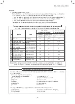


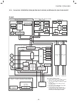


(Indoor unit A)
Refrigerant pipe
at liquid side
(Outer dia : ØA)
Refrigerant pipe
at liquid side
(Outer dia : ØC)
Refrigerant pipe
at gas side
(Outer dia : ØB)
Distributor
(Strainer incorporated)
Strainer
TCJ sensor
TC sensor
Air heat
exchanger
To outdoor unit
Branch pipe
(Indoor unit B)
Refrigerant pipe
at liquid side
(Outer dia : ØA)
Refrigerant pipe
at liquid side
(Outer dia : ØD)
Refrigerant pipe
at gas side
(Outer dia : ØB)
Distributor
(Strainer incorporated)
Strainer
TCJ sensor
TC sensor
To outdoor unit
Branch pipe
Air heat
exchanger
Heating
Cooling
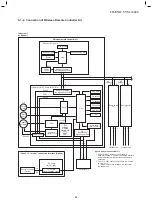
(Indoor unit)
Refrigerant pipe
at liquid side
(Outer dia : ØB)
Refrigerant pipe
at gas side
(Outer dia : ØA)
Distributor
(Strainer incorporated)
Strainer
Heating
Cooling
TCJ sensor
TC sensor
Air heat
exchanger
To outdoor unit
To outdoor unit
• Single type (Combination of 1 indoor unit and 1 outdoor unit)
• Twin type (Combination of 2 indoor units and 1 outdoor unit)
Indoor unit
R
M56
× 2
Branch pipe RBC-
TWP30E2
A
B
C
D
6.4
12.7
9.5
15.9
Dimension table
Indoor unit
R
M56 type
Outer diameter of refrigerant pipe
Gas side ØA
Liquid side ØB
12.7
6.4
R
M80, 110, 140
, 160
type
15.9
9.5
Capillary tube specifications
Model
RAV-
R
M
∗∗∗
UTP
∗
R
M56 type
R
M80 type
R
M110, 140
,
160
type
Inner dia. × Length × Q’ty
Ø2 × 250 × 2, Ø2 × 350 × 1
Ø2 × 700 × 1
Ø2 × 250 × 3, Ø2 × 500 × 1
Ø2 × 200 × 1, Ø2 × 300 × 2
Ø2 × 350 × 2, Ø2 × 700 × 1
2. SYSTEMATIC REFRIGERATING CYCLE DIAGRAM
2-1. Indoor Unit
FILE NO. SVM-18040
- 18 -