


A B
1
1
2
2
3
3
A B
1
2
3
A B
1
1
2
2
3
3
A B
1
2
3
A B
1
2
3
A B
1
2
3
A B
1
2
3
1
2
3
1 2 3
B
A
– 16 –
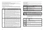
■
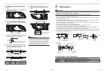
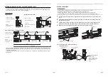
Wiring between indoor unit and outdoor unit
• Figure below shows the wiring connections between the indoor and outdoor units and between the indoor units
and remote controller. The wires indicated by the broken lines or dot-and-dash lines are provided at the locally.
• Refer to the both indoor and outdoor unit wiring diagrams.
Wiring diagram
Single system
Remote controller
Remote controller wiring
Indoor side
System
interconnection wires
Outdoor side
Simultaneous twin system
Remote controller
Remote controller wiring
Indoor side
System interconnection wires
Outdoor side
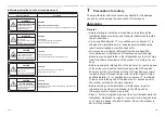
Simultaneous triple and double twin system
Remote controller
inter-unit wiring
Remote controller
Remote controller wiring
Indoor side
System
interconnection wires
Outdoor side
Indoor side
Power supply
Power supply
Power supply
Triple
Double twin
Indoor power
inter-unit wiring
Indoor power
inter-unit wiring
Indoor power
inter-unit wiring
Indoor side
Indoor side
Remote controller
inter-unit wiring
Remote controller
inter-unit wiring
* Use 2-core shield wire (MVVS 0.5 to 2.0 mm
2
or more) for the remote controller wiring in the simultaneous twin,
simultaneous triple and simultaneous double twin systems to prevent noise problems. Connect both ends of the
shield wire to earth leads.
* Connect earth wires for each indoor unit in the simultaneous twin, simultaneous triple and simultaneous double
twin systems.
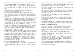
Remote controller
inter-unit wiring
Indoor
side
Indoor power
inter-unit wiring
Electrical control
box cover
P.C. board
Terminal block
System interconnection
wires
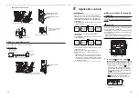
Run the system
interconnection wire here
through the clamp base
and
fi
x it with a cord
clamp.
▼
Connecting the system interconnection wire
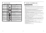
◆
Wire connection
REQUIREMENT
• Connect the wires matching the terminal numbers. Incorrect connection causes a trouble.
• Pass the wires through the bushing of wire connection holes of the indoor unit.
• Keep a margin (Approx. 100 mm) on a wire to hang down the electrical control box at servicing.
• The low-voltage circuit is provided for the remote controller. (Do not connect the high-voltage circuit)
1
Loosen the cover mounting screws (2 positions) of the electrical control box, and then remove the
cover.
2
Connect the system interconnection wires and the remote controller wire to the terminal block of
the electrical control box.
3
Tighten screws of the terminal block securely, and
fi
x the wires with code clamp attached to the
electrical control box. (Do not apply tension to the connecting section of the terminal block.)
4
Mount the cover of the electrical control box so that it does not pinch the wires.
Two screws
Terminal block of
power supply
<Single connection>
Remote controller
terminal block
Earth screw
Clamp base
Cord clamp
System interconnection wires
31-EN
32-EN