


– 14 –
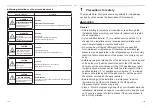
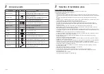
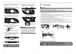
Right
Upper
Back
6
Refrigerant piping
■
Take out direction of
refrigerant pipe
• The refrigerant pipe connecting sections are located
as shown below. (Pipes can be taken out from one of
the three directions.)
• Make a pipe knockout hole, referring to the section
“Pipe knockout hole”.
* When Drain Pump Kit (sold separately) is installed, a
refrigerant pipe can only be taken out from upper direction.
■
Permissible piping length and
height difference
They vary depending on the outdoor unit. For details,
refer to the Installation Manual attached to the outdoor
unit.
CAUTION
IMPORTANT 4 POINTS FOR PIPING WORK
1. Reusable mechanical connectors and
fl
ared
joints are not allowed indoors. When mechanical
connectors are reused indoors, sealing parts shall
be renewed. When
fl
ared joints are reused indoors,
the
fl
are part shall be refabricated.
2. Tight connection (between pipes and unit)
3. Evacuate the air in the connecting pipes by using
VACUUM PUMP.
4. Check the gas leakage. (Connected points)
■
Pipe size
Model
Pipe size (mm)
Gas side
Liquid side
GM90
Ø15.9
Ø9.5
■
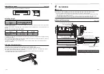
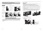
Connecting refrigerant piping
Flaring
• Cut the pipe with a pipe cutter.
Remove burrs completely.
Remaining burrs may cause gas leakage.
• Insert a
fl
are nut into the pipe, and
fl
are the pipe.
As the
fl
aring sizes of R32 differ from those of
refrigerant R22, the
fl
are tools newly manufactured for
R32 are recommended.
However, the conventional tools can be used by
adjusting projection margin of the copper pipe.
Projection margin in
fl
aring: B (Unit: mm)
Outer dia. of
copper pipe
Tool used
Conventional
tool used
6.4, 9.5
0.5 to 1.1
1.0 to 1.5
12.7, 15.9
0.5 to 1.1
1.5 to 2.0
B
CAUTION
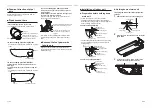
When the refrigerant pipe is long, provide support
brackets at intervals of 2.5 m to 3 m to clamp the
refrigerant pipe. Otherwise, abnormal sound may be
generated.
A
Flaring diameter size: A (Unit: mm)
CAUTION
• Do not scratch the inner surface of the
fl
ared part when
removing burrs.
• Flare processing under the condition of scratches on
the inner surface of
fl
are processing part will cause
refrigerant gas leak.
• Check that the
fl
ared part is not scratched, deformed,
stepped, or
fl
attened, and that there are no chips
adhered or other problems, after
fl
are processing.
• Do not apply refrigerating machine oil to the
fl
are
surface.
* In case of
fl
aring with the conventional
fl
are tool,
pull it out approx. 0.5 mm more than that for R22 to
adjust to the speci
fi
ed
fl
are size. The copper pipe
gauge is useful for adjusting projection margin size.
• The sealed gas was sealed at the atmospheric
pressure so when the
fl
are nut is removed, there
will no “whooshing” sound: This is normal and is not
indicative of trouble.
• Use two wrenches to connect the indoor unit pipe.
Work using double spanner
• Use the tightening torque levels as listed in the table
below.
Outer dia. of
connecting pipe (mm)
Tightening torque (N•m)
6.4
14 to 18 (1.4 to 1.8 kgf•m)
9.5
34 to 42 (3.4 to 4.2 kgf•m)
12.7
49 to 61 (4.9 to 6.1 kgf•m)
15.9
63 to 77 (6.3 to 7.7 kgf•m)
▼
Tightening torque of
fl
are pipe connections.
Incorrect connections may cause not only a gas leak,
but also a trouble of the refrigeration cycle.
Align the centres of the connecting pipes and tighten
the
fl
are nut as far as possible with your
fi
ngers. Then
tighten the nut with a spanner and torque wrench as
shown in the
fi
gure.
CAUTION
Tightening with an excessive torque may crack the nut
depending on installation conditions.
■
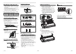
Evacuation
Perform vacuuming from the charge port of valve of
the outdoor unit by using a vacuum pump.
For details, follow to the Installation Manual attached to
the outdoor unit.
• Do not use the refrigerant sealed in the outdoor unit
for evacuation.
REQUIREMENT
For the tools such as charge hose, use those
manufactured exclusively for R32.
Refrigerant amount to be added
For addition of the refrigerant, add refrigerant “R32”
referring to the attached Installation Manual of outdoor
unit.
Use a scale to charge the refrigerant of speci
fi
ed
amount.
REQUIREMENT
• Charging an excessive or too little amount of
refrigerant causes a trouble of the compressor.
Charge the refrigerant of speci
fi
ed amount.
• A personnel who charged the refrigerant should
write down the pipe length and the added refrigerant
amount in the F-GAS label of the outdoor unit. It is
necessary to
fi
x the compressor and refrigeration
cycle malfunction.
Outer dia. of copper pipe
A
+0
–0.4
6.4
9.1
9.5
13.2
12.7
16.6
15.9
19.7
27-EN
28-EN