


– 42 –
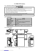
11-1-2. Installation
1. Improvement of electric parts of the indoor unit
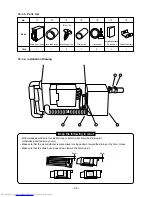
1. Remove the electric parts box from the indoor unit,
and then remove covers of the terminal block and
electric parts. (Fig. 11-1-1)
2.
Insert card spacer
…
to the rear side of the electric
parts box, and mount mini P.C. board
„
on it.
(Fig. 11-1-2)
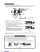
3. Insert connector of mini P.C. board
„
into CN24 of
the main P.C. board. (Fig. 11-1-3)
4. Cut the resistance R29 and R92 on the main P.C.
board. (Fig. 11-1-4)
Fig. 11-1-1
Fig. 11-1-2
Fig. 11-1-3
Fig. 11-1-4
2. Installation of relay unit
1.
U sing 3 screw s
†
, fix relay unit
•
to the opposite side to the
electric parts box of the indoor unit. (Fig. 11-1-5)
2. Insert the lead wires of relay unit
•
into connector (CN201) on mini
P.C. board
„
and CN23 of the main P.C. board. (Fig. 11-1-6)
Using the cord clamp, fix the lead wires to be connected to CN201.
3. Mount each cover of the electric parts box, and then mount the
electric parts box to the indoor unit.
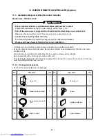
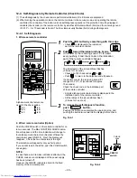
3. Connection of remote controller cable
1. Fit the application terminal side of remote controller cable
ƒ
to the
terminal block side of relay unit
•
, and then connect cable by
matching letters on wired remote controller
‚
, A, B, and C to those
on the terminal block. (Fig. 11-1-7)
Fig. 11-1-7
Fig. 11-1-5
Fig. 11-1-6
Summary of Contents for RAS-M10YDCV-E
Page 62: ......