


No. Part name
Procedure
Remarks
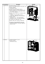
③
Inverter
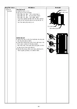
10) Disconnect the leads connected to the other
assembly
parts from the P.C. assembly.
(continued)
These connectors have the lock. The lock must
be released before they are disconnected.
Main P.C. board
CN300 : Outdoor fan motor (3P : white)
CN500 : Thermostat for compressor (2P : blue)
CN501 : High pressure switch (3P : green)
Control P.C. board
CN01 : AC-IN (2P : Red)
CN02 : S
erial
co
mm
unication (3P : Black)
CN600 : TD sensor (3P : white)
CN602 : TO sensor (2P : white)
CN604 : TGa sensor (2P : yellow)
CN605 : TGb sensor (2P : red)
CN606 : TGc sensor (2P : green)
CN700 : PMV A (6P : yellow)
CN701 : PMV B (6P : red)
CN702 : PMV C (6P : green)
CN805 : Display P.C. board (10P : white)
Connected connector of main and control
CN806 and CN802 (5P : blue)
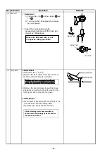
11) Remove the heatsink.
(ST2TØ3×12L 5pcs.)
12) Remove the PCB base.
When mounting the new control board assembly,
ensure that the P.C. board is inserted properly into
the P.C. board support groove.
- 82 -