


8
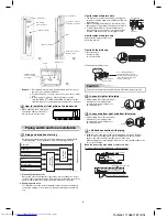
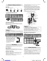
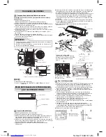
1. Connect the charge hose from the manifold valve to the service port of
the packed valve at gas side.
2. Connect the charge hose to the port of the vacuum pump.
3. Open fully the low pressure side handle of the gauge manifold valve.
4. Operate the vacuum pump to start evacuating. Perform evacuating for
about 15 minutes if the piping length is 20 meters. (15 minutes for 20
meters) (assuming a pump capacity of 27 liters per minute) Then confi rm
that the compound pressure gauge reading is –101 kPa (–76 cmHg).
5. Close the low pressure side valve handle of the gauge manifold valve.
6. Open fully the valve stem of the packed valves (both gas and liquid
sides).
7. Remove the charging hose from the service port.
8. Securely tighten the caps on the packed valves.
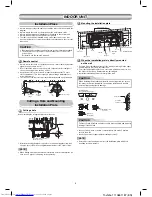
Wiring Connection
1. Remove the valve cover, the electric parts cover and the cord clamp from
the outdoor unit.
2. Connect the connecting cable to the terminal as identifi ed by the matching
numbers on the terminal block of indoor and outdoor unit.
3. Insert the power cord and the connecting cable carefully into the terminal
block and secure it tightly with screws.
4. Use vinyl tape, etc. to insulate the cords which are not going to be used.
Locate them so that they do not touch any electrical or metal parts.
5. Secure the power cord and the connecting cable with the cord clamp.
6. Attach the electric parts cover and the valve cover on the outdoor unit.
Pressure gauge
Manifold valve
–101 kPa (–76 cmHg)
Handle Lo
Connecting pipe
Compound pressure gauge
Vacuum
pump
Handle Hi
(Keep full closed)
Charge hose
(For R410A only)
Vacuum pump adapter for
counter-fl ow prevention
(For R410A only)
Service port (Valve core (Setting pin))
Packed valve at liquid side
Packed valve at gas side
Charge hose
(For R410A only)
A
90
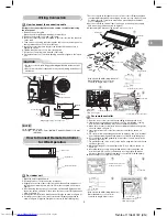
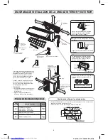
Refrigerant Piping Connection
Tightening connection
Align the centers of the connecting pipes and tighten the fl are nut as far as
possible with your fi ngers. Then tighten the nut with a spanner and torque
wrench as shown in the fi gure.
(Unit : N·m)
Outer dia. of copper pipe
Tightening torque
6.35 mm
14 to 18 (1.4 to 1.8 kgf·m)
12.70 mm
50 to 62 (5.0 to 6.2 kgf·m)
Evacuating
Tightening torque for connection of fl are pipe
The pressure of R410A is higher than R22.
(Approx. 1.6 times.) Therefore securely
tighten the fl are pipes which connect the
outdoor unit and the indoor unit with the
specifi ed tightening torque using a torque
wrench. If any fl are pipe is incorrectly
connected, it may cause not only
a gas leakage but also trouble in the
refrigeration cycle.
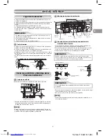
Flaring
1. Cut the pipe with a pipe cutter.
Obliquity
Roughness
Warp
Half union
Flare nut
Pipe
Die
Flare at
outdoor unit side
Flare at
indoor unit side
Use a wrench to secure.
Use a torque wrench to tighten.
2. Insert a fl are nut into the pipe and fl are the pipe.
Projection margin in fl aring : A (Unit : mm)
CAUTION
Do not apply excess torque. Otherwise, the nut may crack depending on
the conditions.
Internally
threaded side
Externally
threaded side
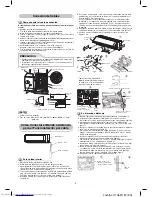
After the piping has been connected to the indoor unit, you can perform
vacuuming together at once.
Using a vacuum pump
Be sure to use a vacuum pump with counter-fl ow prevention function so
that inside oil of the pump does not fl ow backward into pipes of the air
conditioner when the pump stops.
(If oil inside of the vacuum pump enters the air conditioner, which use
R410A, refrigeration cycle trouble may happen.)
Rigid (clutch type)
Outer dia.
of copper pipe
R410A tool used
Conventional
tool used
6.35 mm
0 to 0.5
1.0 to 1.5
12.70 mm
0 to 0.5
1.0 to 1.5
Imperial (wing nut type)
Outer dia. of copper pipe
R410A
6.35 mm
1.5 to 2.0
12.70 mm
2.0 to 2.5
CAUTION
KEEP IMPORTANT 5 POINTS FOR PIPING WORK.
(1) Take away dust and moisture (inside of the connecting pipes).
(2) Tighten the connections (between pipes and unit).
(3) Evacuate the air in the connecting pipes using a VACUUM PUMP.
(4) Check gas leak (connected points).
(5) Be sure to fully open the packed valves before operation.
VACUUMING
Evacuate the air in the connecting pipes and in the indoor unit using a
vacuum pump. Do not use the refrigerant in the outdoor unit. For details, see
the manual of the vacuum pump.
Packed valve handling precautions
•
Open the valve stem all the way out, but do not try to open it beyond the
stopper.
Pipe size of Packed Valve
Size of Hexagon wrench
12.70 mm and smallers
A = 4 mm
15.88 mm
A = 5 mm
•
Securely tighten the valve cap with torque in the following table:
Cap
Cap Size (H )
Torque
Valve Rod
Cap
H17 - H19
14~18 N·m
(1.4 to 1.8 kgf·m)
H22 - H30
33~42 N·m
(3.3 to 4.2 kgf·m)
Service Port
Cap
H14
8~12 N·m
(0.8 to 1.2 kgf·m)
H17
14~18 N·m
(1.4 to 1.8 kgf·m)
A
H
Hexagon wrench
is required.
Service Port Cap
Valve Rod Cap
Toshiba 1110651187 (EN)
Summary of Contents for RAS-18N3ACV Series
Page 57: ...MEMO Toshiba 1110651187 MEMO ...
Page 58: ...MEMO Toshiba 1110651187 MEMO ...
Page 59: ...Toshiba 1110651187 MEMO ...
Page 60: ...Toshiba 1110651187 COVER_B ...