


The power supply can be selected to connect to indoor unit or outdoor unit. Choose proper way and connect the power supply and connecting cable by
follow the instruction as following.
Wiring of the cable can be carried out without removing the main panel.
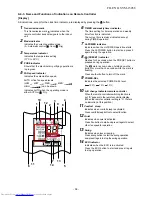
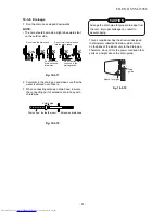
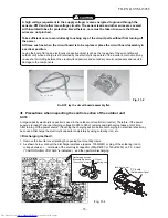
1. Remove the front panel.
Pull and lift up front panel until it stops, move arms on left and right
side to outward direction then pull toward you to remove front panel.
w Beware front panel fall down that may cause of injure or part
damage.
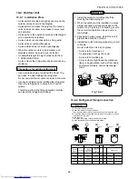
2. Remove the terminal cover and cord clamp.
3. Insert the cable (according to the local cords) into the pipe hole on the
wall.
4. Take out the cable protrudes about 20 cm from the front.
5. Insert the cable fully into the terminal block and secure it tightly with
screws.
6. Tightening torque : 1.2 N·m (0.12 kgf·m)
7. Secure the cable with the cord clamp.
8. Fix the terminal cover and attach front panel to the indoor unit.
Cable
about 20 cm
Front panel
Terminals block
Main panel
Terminal cover
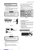
1. Remove the valve cover from the outdoor unit.
2. Connect the cable to the terminals as identifi ed with their respective
matched numbers on the terminal block of indoor and outdoor unit.
3. When connecting the cable to the outdoor unit terminals, make a loop as
shown in the installation diagram of indoor and outdoor unit to
prevent water coming in the outdoor unit.
4. Insulate the unused cords (conductors) from any water coming in the
outdoor unit. Proceed them so that they do not touch any electrical
or metal parts.
10-5-1. Wiring Connection
Indoor unit
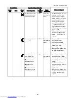
Carry out attaching in the reverse order to removal.
Keep front panel horizontally and put both arms into guides.
Make sure both arms are inserted completely.
If the gap between main panel and front panel isn’t even, remove and
attach again.
How to attach the front panel
Valve cover
Terminals block
10-5. Electrical works
• Check local electrical cords and also any specifi c wiring instructions or
Outdoor unit
• Be sure to refer to the wiring system diagram labeled inside the
main panel.
limitations.
CAUTION
Fig. 10-
5
-
1
Fig. 10-
5
-
2
Fig. 10-
5
-
3
Fig. 10-
5
-
4
Arm
Arm
Guide
Arm
Main panel
Front panel
Gap between main
panel and front panel
should be even.
Model
RAS-10G2KCVP-T
RAS-13G2KCVP-T
RAS-18G2KCVP-T
Power source
50Hz, 220V Single phase
Maximum running current
4.75A
6.04A
9.00A
Circuit breaker rating
6.0A
7.5A
12.0A
Wire type :
Power supply cable
More than H07RN-F or 60245 IEC66 (1.5 mm
2
or more)
Connecting cable
More than H07RN-F or 60245 IEC66 (1.5 mm
2
or more)
FILE NO. SVM-15058
- 71 -
Summary of Contents for RAS-18G2ACVP-T
Page 18: ...5 WIRING DIAGRAM FILE NO SVM 15058 18 ...
Page 122: ......