Toshiba RAS-10G2AVP Series Installation Manual Download Page 3

EN

EN

FR

IT

DE

PT

PL

CZ

RU

CR

HU

TR

NL

GR

SV

FI

NO

DK

RO

BG

EE

LV

SK

SI

1

PRECAUTIONS FOR SAFETY

PRECAUTIONS FOR SAFETY

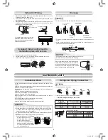
New refrigerant air conditioner installation

CAUTION

•  THIS AIR CONDITIONER USES THE NEW HFC REFRIGERANT (R410A), WHICH DOES NOT DESTROY THE OZONE LAYER.

  R410A refrigerant is apt to be affected by impurities such as water, oxidizing membranes, and oils because the pressure of R410A refrigerant is approx. 

1.6 times of refrigerant R22. As well as the adoption of this new refrigerant, refrigerating machine oil has also been changed. Therefore, during installation 
work, be sure that water, dust, former refrigerant, or refrigerating machine oil does not enter the refrigeration cycle of a new-refrigerant air conditioner.

  To avoid mixing refrigerant and refrigerating machine oil, the sizes of charging port connecting sections on the main unit are different from those for the 

conventional refrigerant, and different size tools are also required. For connecting pipes, use new and clean piping materials with high pressure withstand 
capabilities, designed for R410A only, and ensure that water or dust does not enter. Moreover, do not use any existing piping as its pressure withstand 
may be insuf

fi

 cient and may contain impurities.

DANGER

•  FOR USE BY QUALIFIED PERSONS ONLY.
•  MEANS FOR DISCONNECTION FROM THE SUPPLY HAVING A CONTACT SEPERATION OF AT LEAST 3 mm IN ALL POLES MUST BE 

INCORPORATED IN THE FIXED WIRING.

•  TURN OFF MAIN POWER SUPPLY BEFORE ATTEMPTING ANY ELECTRICAL WORK. MAKE SURE ALL POWER SWITCHES ARE OFF. FAILURE 

TO DO SO MAY CAUSE ELECTRIC SHOCK.

•  CONNECT THE CONNECTING CABLE CORRECTLY. IF THE CONNECTING CABLE IS CONNECTED WRONGLY, ELECTRIC PARTS MAY BE 

DAMAGED.

•  CHECK THE EARTH WIRE THAT IT IS NOT BROKEN OR DISCONNECTED BEFORE INSTALLATION.
•  DO NOT INSTALL NEAR CONCENTRATIONS OF COMBUSTIBLE GAS OR GAS VAPORS. FAILURE TO FOLLOW THIS INSTRUCTION CAN 

RESULT IN FIRE OR EXPLOSION.

•  TO PREVENT OVERHEATING THE INDOOR UNIT AND CAUSING A FIRE HAZARD, PLACE THE UNIT WELL AWAY (MORE THAN 2 M) FROM 

HEAT SOURCES SUCH AS RADIATORS, HEATERS, FURNACE, STOVES, ETC.

•  WHEN MOVING THE AIR CONDITIONER FOR INSTALLING IT IN ANOTHER PLACE AGAIN, BE VERY CAREFUL NOT TO GET THE SPECIFIED 

REFRIGERANT (R410A) WITH ANY OTHER GASEOUS BODY INTO THE REFRIGERATION CYCLE. IF AIR OR ANY OTHER GAS IS MIXED IN 
THE REFRIGERANT, THE GAS PRESSURE IN THE REFRIGERATION CYCLE BECOMES ABNORMALLY HIGH AND IT RESULTINGLY CAUSES 
BURST OF THE PIPE AND INJURIES ON PERSONS.

•  IN THE EVENT THAT THE REFRIGERANT GAS LEAKS OUT OF THE PIPE DURING THE INSTALLATION WORK, IMMEDIATELY LET FRESH AIR 

INTO THE ROOM. IF THE REFRIGERANT GAS IS HEATED BY FIRE OR SOMETHING ELSE, IT CAUSES GENERATION OF POISONOUS GAS.

•  WHEN INSTALLING OR RE-INSTALLING THE AIR CONDITIONER, DO NOT INJECT AIR OR OTHER SUBSTANCES BESIDES THE DESIGNATED 

REFRIGERANT “R410A” INTO THE REFRIGERATING CYCLE. IF AIR OR OTHER SUBSTANCES ARE MIXED, AN ABNORMAL PRESSURE CAN 
OCCUR IN THE REFRIGERATING CYCLE, AND THIS CAN CAUSE AN INJURY DUE TO A PIPE RUPTURE.

For general public use

Power supply cord of parts of appliance shall be at least polychloroprene sheathed 

fl

 exible cord (design H07RN-F) or cord designation 60245 IEC66 

(1.5 mm

2

 or more). (Shall be installed in accordance with national wiring regulations.)

The manufacturer shall not assume any liability for the damage caused by not observing the description of this manual.
Be sure to read this installation manual carefully before installing.
Recommend to the owner to perform maintenance periodically when using over long periods of time.
Be sure to follow the precautions provided here to avoid safety risks. The symbols and their meanings are shown below.

DANGER : 

It indicates that incorrect use of this unit can result in a high possibility of severe injury (*1) or death.

WARNING : 

It indicates that incorrect use of this unit may cause severe injury or death.

CAUTION : 

It indicates that incorrect use of this unit may cause personal injury (*2), or property damage (*3).


  *1 :  A severe injury refers to blindness, injury, burns (hot or cold), electrical shock, bone fracture, or poisoning that leaves aftereffects and 

requires hospitalization or extended out-patient treatment.


  *2 :  Personal injury means a slight accident, burn, or electrical shock which does not require admission or repeated hospital treatment.


  *3 :  Property damage means greater damage which affects assets or resources.

1115751104-EN.indd   1

1115751104-EN.indd   1

5/26/2557 BE   10:45 AM

5/26/2557 BE   10:45 AM

Summary of Contents for RAS-10G2AVP Series

Page 1: ...VP Series RAS 16G2KVP Series Outdoor unit RAS 10G2AVP Series RAS 13G2AVP Series RAS 16G2AVP Series AIR CONDITIONER SPLIT TYPE INSTALLATION MANUAL 1115751104 1115751104 EN indd 1 1115751104 EN indd 1 5 26 2557 BE 10 45 AM 5 26 2557 BE 10 45 AM ...

Page 2: ... OUTDOOR UNIT 6 Installation Place 6 Refrigerant Piping Connection 6 Evacuating 7 ELECTRICAL WORKS 8 Wiring Connection 8 Power Supply and Connecting Cable Connection 9 Power supply input Wiring Diagram 10 Wiring between DRED Demand response enabling device and Outdoor Unit 11 Connection procedure 11 Outdoor unit preparation 12 OTHERS 13 Gas Leak Test 13 Remote Control A B Selection 13 Test Operati...

Page 3: ...T IN ANOTHER PLACE AGAIN BE VERY CAREFUL NOT TO GET THE SPECIFIED REFRIGERANT R410A WITH ANY OTHER GASEOUS BODY INTO THE REFRIGERATION CYCLE IF AIR OR ANY OTHER GAS IS MIXED IN THE REFRIGERANT THE GAS PRESSURE IN THE REFRIGERATION CYCLE BECOMES ABNORMALLY HIGH AND IT RESULTINGLY CAUSES BURST OF THE PIPE AND INJURIES ON PERSONS IN THE EVENT THAT THE REFRIGERANT GAS LEAKS OUT OF THE PIPE DURING THE ...

Page 4: ...bsorbed and abnormal high pressure inside the refrigeration cycle and resulting burst or injury Do not modify the power cable connect the cable midway or use a multiple outlet extension cable Doing so may cause contact failure insulation failure or excess current resulting in fire or electrical shock Do not use any refrigerant different from the one specified for complement or replacement Otherwis...

Page 5: ...or the rear left and left piping Wall Make sure to run the drain hose sloped downward Do not allow the drain hose to get slack Cut the piping hole sloped slightly The auxiliary piping can be connected to the left rear left rear right right bottom right or bottom left Right Rear right Bottom right Rear left Bottom left Left 1 Batteries Flat head wood screw Remote control holder Vinyl tape Apply aft...

Page 6: ...ted in the below figure 3 Install the installation plate horizontally in the wall When installing the installation plate with a mounting screw do not use the anchor bolt holes Otherwise the unit may fall down and result in personal injury and property damage 1 After determining the pipe hole position on the mounting plate drill the pipe hole Ø65 mm at a slight downward slant to the outdoor side A ...

Page 7: ...cation causes deterioration and drain leakage of the plug No gap Insert a hexagon wrench 4 mm 326 mm 283 mm 43 mm 80 Liquid side Gas side To the forefront of flare Outward form of indoor unit R 30 mm Use polisin polyethylene core or the like for bending pipe Use the handle of screwdriver etc Slit Cap Slit NOTE If the pipe is bent incorrectly the indoor unit may unstably be set on the wall After pa...

Page 8: ...w which forms on the back of the indoor unit to the drain pan Therefore do not store the power cord and other parts at a height above the drain guide CAUTION OUTDOOR UNIT OUTDOOR UNIT Installation Place A place which provides the spaces around the outdoor unit as shown in the diagram A place which can bear the weight of the outdoor unit and does not allow an increase in noise level and vibration A...

Page 9: ...10A refrigeration cycle trouble may result 1 Connect the charge hose from the manifold valve to the service port of the packed valve at gas side 2 Connect the charge hose to the port of the vacuum pump 3 Open fully the low pressure side handle of the gauge manifold valve 4 Operate the vacuum pump to start evacuating Perform evacuating for about 15 minutes if the piping length is 25 meters 15 minut...

Page 10: ... with the cord clamp 8 Fix the terminal cover and attach front panel to the indoor unit Cable about 20 cm Front panel Terminals block Main panel Terminal cover 1 Remove the valve cover from the outdoor unit 2 Connect the cable to the terminals as identified with their respective matched numbers on the terminal block of indoor and outdoor unit 3 When connecting the cable to the outdoor unit termina...

Page 11: ...Stripping length of the connecting cable 3 Connecting cable 50 mm 45 mm 10 mm Earth line about 20 cm Power Supply Input at Outdoor Unit Terminal Block Optional Indoor Unit Outdoor Unit Connecting CABLE Connecting cable connect to terminal block 3 Connecting cable connect to terminal block L N Stripping length of the connecting cable 3 N L Connecting cable 50 mm 90 mm 10 mm Earth line about 20 cm 4...

Page 12: ...t burn out 8 Incorrect or incomplete wiring is carried out it will cause an ignition or smoke 9 This product can be connected to main power supply Connection to fixed wiring A switch which disconnects all poles and has a contact separation at least 3mm must be incorporated in the fixed wiring Power supply input Wiring Diagram Indoor Terminal Block Power supply input Outdoor Terminal Block Indoor T...

Page 13: ...ectric shock fire or refrigerant leak Wear heavy gloves during the installation work to avoid injury CAUTION Connection procedure This air conditioner complies with AS NZS 4755 3 1 DRM available DRM1 DRM2 DRM3 The terminal block meets ELV requirements COM DRM1 DRM2 DRM3 COM DRM1 DRM2 DRM3 CN01 WHI CN102 IC103 C100 DB100 C103 D101 COM DRM1 DRM2 DRM3 10 30 COM DRM1 DRM2 DRM3 Stripping length for DRE...

Page 14: ...Front cabinet 5 Left side of front cabinet is inserted into Left side cabinet remove by lift up the front cabinet 6 Slide the DRI cover to open for wire connection 7 Connect DRED wires to the terminal of DRM 8 Reassembly by reverse process Upper cabinet Water proof cover Valve cover 5 4 Demand response interface DRI 6 Demand response interface DRI DRI cover Outdoor unit preparation 3 1115751104 EN...

Page 15: ...nt two rooms if operating a unit two units may receive the remote control signal simultaneously and operate In this case the operation can be preserved by setting either one remote control to B setting Both are set to A setting in factory shipment The remote control signal is not received when the settings of indoor unit and remote control are different There is no relation between A setting B set...

Page 16: ...1115751104 1115751104 EN indd 14 1115751104 EN indd 14 5 26 2557 BE 10 45 AM 5 26 2557 BE 10 45 AM ...

Reviews: