


EN
EN
FR
IT
DE
PT
PL
CZ
RU
CR
HU
TR
NL
GR
SV
FI
NO
DK
RO
BG
EE
LV
SK
SI
13
OTHERS
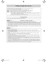
OTHERS
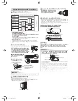
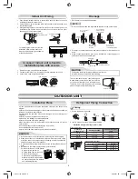
Gas Leak Test
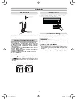
Test Operation
To switch to the TEST RUN (COOL) mode, press Temporary switch for
10 seconds. (The unit will make a short Pi sound.)
Auto Restart Setting
The product was shipped with Auto Restart function in the off position.
Turn it on as required.
Remote Control A-B Selection
To separate using of remote control for each indoor unit in case of 2 air
conditioner are installed near.
Remote Control B Setup.
1. Press RESET button on the indoor unit to turn the air conditioner ON.
2. Point the remote control at the indoor unit.
3. Push and hold
button on the Remote Control by the tip of the pencil.
“00” will be shown on the display.
4. Press
during pushing
. “B” will show on the display and “00” will
disappear and the air conditioner will turn OFF. The Remote Control B is
memorized.
Note : 1. Repeat above step to reset Remote Control to be A.
2. Remote Control A has not “A” display.
3. Default setting of Remote Control from factory is A.
• When two indoor units are installed in the same room or adjacent two
rooms, if operating a unit, two units may receive the remote control signal
simultaneously and operate. In this case, the operation can be preserved
by setting either one remote control to B setting. (Both are set to A setting
in factory shipment.)
• The remote control signal is not received when the settings of indoor unit
and remote control are different.
• There is no relation between A setting/B setting and A room/B room when
connecting the piping and cables.
This product is designed so that, after a power failure, it can restart
automatically in the same operating mode as before the power failure.
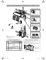
Check places for
the indoor unit.
Check places for
the outdoor unit.
Information
• Check the
fl
are nut connections for the gas leak with a gas leak detector or
soap water.
How to set the Auto Restart
1. Press and hold the Temporary switch on the indoor unit for 3 seconds to
set the operation (3 Pi sound and OPERATION lamp blink 5 time/sec for
5 seconds).
2. Press and hold the Temporary switch on the indoor unit for 3 seconds to
cancel the operation (3 Pi sound but OPERATION lamp does not blink).
• In case of ON timer or OFF timer are set, AUTO RESTART OPERATION
does not activate.
Temporary switch
1115751104-EN.indd 13
1115751104-EN.indd 13
5/26/2557 BE 10:45 AM
5/26/2557 BE 10:45 AM