


FILE NO. SVM-02003
– 42 –
D
C
A
B
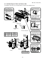
8-7. Others
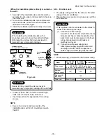
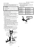
8-7-1. Gas leak test
For RAS-10UASX, RAS-07UAX-T2
Fig. 8-7-1
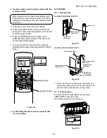
For RAS-13UAX-T2, RAS-10UAX-T2
•
Check the flare nut connections, valve stem cap
connections and service port cap connections for
gas leak with a leak detector or soap water.
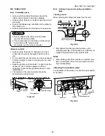
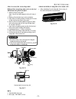
8-7-2. Test operation
To switch the TEST RUN (COOL) mode, press
TEMPORARY button for 10 sec.
(The beeper will make a short beep.)
Fig. 8-7-3
Valve stem cap connection
Flare nut connections
(Outdoor unit)
Electric parts cover
Flare nut connections
(indoor unit)
Valve stem cap
connection
Service cap
connection
Valve stem cap
connection
Service cap
connection
Valve cover
Fig. 8-7-2
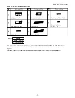
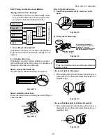
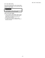
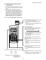
2. Set the remote control selector switch with the
remote control
[B] is indicated on the liquid crystal display when
setting remote control selector switch to B. [A] is not
indicated on the display even if the selector switch
is set to A.
1) Load the remote control with the batteries.
2) Press the [CHECK] button using something with
sharp point. (The preset temperature on the remote
control changes to [00].)
3) Press the [MODE] button while pressing the
[CHECK] button, [B] is indicted at the right of the
present temperature display.
•
To reset the switch to the [A] setting, press the
[MODE] button again while pressing the [CHECK]
button.
Fig. 8-6-2
3. Confirm that the indoor unit can operate with
the new setting.
[MODE] button
[CHECK] button
PRESET
FAN
MODE
Hi-POWER
ON
OFF
SET
CLR
ECO
AUTO
TIMER
CLOCK CHECK
RESET
FILTER
FIX
SWING
MEMO
START/STOP
A
B
A
B
TEMPORARY button
TEMPORARY button