background image

– 89 –

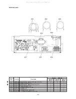
Location

No.

401
402
403
404
405
406
407
408

Part No.

43050425
43F50426
43150320
43158182
43160575
43160582

4316V587
4316V345

Description

SENSOR ASSY, SERVICE, TC (F6) : TC2, TCJ
SENSOR, SERVICE, TA
SENSOR ASSY, SERVICE, TG (F4) : TC1
TRANSFORMER, TT-12
TERMINAL BLOCK, 2P, 20A
TERMINAL, 4P
P. C. BOARD ASSY, MCC-1403
P. C. BOARD ASSEMBLY, MCC-1520

Q'ty/Set        MML-AP

0074

H2UL

2
1
1
1
1
1
1
1

0094

H2UL

2
1
1
1
1
1
1
1

0124

H2UL

2
1
1
1
1
1
1
1

0154

H2UL

2
1
1
1
1
1
1
1

0184

H2UL

2
1
1
1
1
1
1
1

0244

H2UL

2
1
1
1
1
1
1
1

Electrical parts

All manuals and user guides at all-guides.com

Summary of Contents for MML-AP0074BH2UL

Page 1: ...MULTI TYPE Floor Console Exposed Type MML AP0074H2UL MML AP0094H2UL MML AP0124H2UL MML AP0154H2UL MML AP0184H2UL MML AP0244H2UL Floor Console Recessed Type MML AP0074BH2UL MML AP0094BH2UL MML AP0124BH2UL MML AP0154BH2UL MML AP0184BH2UL MML AP0244BH2UL All manuals and user guides at all guides com a l l g u i d e s c o m ...

Page 2: ... 10 3 WIRING DIAGRAM 16 4 PARTS RATING 18 5 REFRIGERATING CYCLE DIAGRAM 19 6 CONTROL OUTLINE 20 7 APPLIED CONTROL AND FUNCTION 26 8 TROUBLESHOOTING 47 9 DETACHMENTS 69 10 P C BOARD EXCHANGE PROCEDURES 81 11 EXPLODED VIEWS AND PARTS LIST 87 All manuals and user guides at all guides com ...

Page 3: ...the users due to troubles of the product after installation when an incorrect work has been executed Mark Explanation Indicates prohibited items Forbidden to do The sentences near an illustrated mark describe the concrete prohibited contents Indicates mandatory items Compulsory to do The sentences near an illustrated mark describe the concrete mandatory contents Indicates cautions Including danger...

Page 4: ...sure may be generated in the refrigeration cycle which may result in a failure or explosion of the product or an injury to your body For an air conditioner which uses R410A never use other refrigerant than R410A For an air conditioner which uses other refrigerant R22 etc never use R410A If different types of refrigerant are mixed abnormal high pressure generates in the refrigeration cycle and an i...

Page 5: ...des a large amount of charged refrigerant such as a multi air conditioner in a sub room it is necessary that the density does not the limit even if the refrigerant leaks If the refrigerant leaks and exceeds the limit density an accident of shortage of oxygen is caused For the installation moving reinstallation work follow to the Installation Manual If an incorrect installation is done a trouble on...

Page 6: ...y impurities such as water oxide scales oil etc Use clean pipes Be sure to braze with flowing nitrogen gas Never use any other gas except for nitrogen 4 For the ground protection use a vacuum pump for air purge 5 R410A refrigerant is azeotropic mixture type refrigerant Therefore use liquid type to charge the refrigerant If using gas for charging composition of the refrigerant changes and then char...

Page 7: ... R22 are necessary as the general tools 1 Vacuum pump Use vacuum pump by attaching vacuum pump adapter 7 Screwdriver 2 Torque wrench 8 Spanner or Monkey wrench 3 Pipe cutter 9 Hole core drill 4 Reamer 10 Hexagon wrench Opposite side 4mm 5 Pipe bender 11 Tape measure 6 Level vial 12 Metal saw Also prepare the following equipments for other installation method and run check 1 Clamp meter 3 Insulatio...

Page 8: ...ride tube Sound puressure level High Mid Low 1 208V dB A 39 38 35 39 38 35 47 44 40 47 44 40 230V dB A 42 40 38 42 40 38 50 46 42 50 46 42 Model name MML AP0184H2UL AP0244H2UL Cooling capacity kBtu h 18 0 24 0 Heating Capacity kBtu h 20 0 27 0 Electrical Power supply 230V 208V 230V 1phase 60Hz charastaristics Power consumption 208V kW 0 098 0 098 230V kW 0 113 0 113 Appearance Silky shade Munsell ...

Page 9: ...be Sound puressure level High Mid Low 1 208V dB A 40 36 33 40 36 33 40 36 33 40 36 33 230V dB A 42 39 36 42 39 36 42 39 36 43 39 36 Model name MML AP0184BH2UL AP0244BH2UL Cooling capacity kBtu h 18 0 24 0 Heating Capacity kBtu h 20 0 27 0 Electrical Power supply 230V 208V 230V 1phase 60Hz charastaristics Power consumption 208V kW 0 095 0 104 230V kW 0 114 0 120 Appearance Zinc hot dipping steel pl...

Page 10: ...10 Mounting hole wall Mounting hole Floor 2 CONSTRUCTION VIEWS EXTERNAL VIEWS 2 1 Floor Console Exposed Type MML AP0074H2UL AP0094H2UL AP0124H2UL Unit in mm All manuals and user guides at all guides com ...

Page 11: ... 11 Mounting hole wall Mounting hole Floor MML AP0154H2UL AP0184H2UL Unit in mm All manuals and user guides at all guides com a l l g u i d e s c o m ...

Page 12: ... 12 Mounting hole wall Mounting hole wall MML AP0244H2UL Unit in mm All manuals and user guides at all guides com ...

Page 13: ...air filter is cleaned There is a possibility of duct and dust accumulation due to construction debris 3 Provide proper access for the filter replacement or filter cleaning 4 Make sure the service switch is turned off before accessing any internal components of the unit which includes filter replacement Mounting hole Floor 2 2 Floor Console Recessed Type MML AP0074BH2UL AP0094BH2UL AP0124BH2UL Unit...

Page 14: ...r filter is provided with the unit Before starting the unit please make sure the air filter is cleaned There is a possibility of duct and dust accumulation due to construction debris 3 Provide proper access for the filter replacement or filter cleaning 4 Make sure the service switch is turned off before accessing any internal components of the unit which includes filter replacement All manuals and...

Page 15: ...er is provided with the unit Before starting the unit please make sure the air filter is cleaned There is a possibility of duct and dust accumulation due to construction debris 3 Provide proper access for the filter replacement or filter cleaning 4 Make sure the service switch is turned off before accessing any internal components of the unit which includes filter replacement All manuals and user ...

Page 16: ...1 Floor Console Exposed Type MML AP0074H2UL AP0094H2UL AP0124H2UL AP0154H2UL AP0184H2UL AP0244H2UL Flow selector unit Ground screw Indoor unit Ground screw All manuals and user guides at all guides com a l l g u i d e s c o m ...

Page 17: ...2 Floor Console Recessed Type MML AP0074BH2UL AP0094BH2UL AP0124BH2UL AP0154BH2UL AP0184BH2UL AP0244BH2UL Flow selector unit Ground screw Indoor unit Ground screw All manuals and user guides at all guides com ...

Page 18: ...2 C T 0 24 Ø6 size lead wire length 47 1200 mm Vinyl tube Red r o s n e s J C T Floor Console Recessed Type Model MML AP 0074BH 0094BH 0124BH 0154BH 0184BH 0244BH AF 200 70 4KU SWA 200U19A4B r o t o m n a F AC400 V 2 5 μF AC450 V 1 μF AC450 V 1 5 μF r o t o m n a f r o f r e s n e d n o c g n i n n u R TT 12 r e m r o f s n a r T EDM MD12TF 3 r o t o m e s l u P EFM 40YGTF EDM B25YGTF e v l a v r ...

Page 19: ...N082 6P Blue 1 Controls super heat in cooling operation 2 Controls subcool in heating operation 3 Recovers refrigerant oil in cooling operation 4 Recovers refrigerant oil in heating operation Connector CN104 2P White 1 Detects indoor suction temperature Connector CN100 3P Brown 1 Controls PMV super heat in cooling operation Connector CN101 2P Blue 1 Controls PMV subcool in heating operation Connec...

Page 20: ... the operation mode command on the remote control 1 Adjustment range Remote control setup temperature F C Remarks Wired type Wireless type COOL DRY 64 F 18 C to 84 F 29 C 63 F 17 C to 86 F 30 C HEAT 64 F 18 C to 84 F 29 C 63 F 17 C to 86 F 30 C 2 Using the Item code 06 the setup temperature in heating operation can be corrected Default setting Unless the sensor of the remote control is controlled ...

Page 21: ... S5 S3 S0 Thermostat off control by a wired remote control sensor is the same as thermostat off control by an indoor unit sensor If the fan speed has been changed once it is not changed for 3 minutes However when the air volume changes the fan speed changes When cooling operation has started select a downward slope for the fan speed that is the high position If the temperature is just on the diffe...

Page 22: ... TC2 sensor and TCJ sensor is compared with temperature of TC1 sensor and then the lower temperature is used to set the upper limit of the fan tap When B zone has continued for 6 minutes the opera tion shifts to C zone In defrost time the control point is set to 10 8 F 6 C TCJ Temperature of indoor heat exchanger sensor TC1 Temperature of indoor heat exchanger sensor In D and E zones priority is g...

Page 23: ... In N zone the timer count is interrupted and held When shifting to M zone again the timer count restarts and continues If L zone is detected the timer is cleared and the operation returns to normal operation Reset conditions 1 TC1 54 F 12 C and TC2 54 F 12 C and TCJ 54 F 12 C 2 20 minutes passed after stop P2 Q2 F C L N M value When the power supply is turned on the thermostat is forced to turn o...

Page 24: ...he following cases Case when selecting COOL or HEAT by using the remote control Case under READY status for operation Case when protective control worked 1 The filter sign is displayed with LC by sending the filter reset signal to the remote control when the specified time 150H elapsed as a result of integration of the operation time of the indoor fan 2 The integrated timer is cleared when the fil...

Page 25: ...ed thermostat OFF HEAT operation is unavailable because at least one indoor unit is operating in COOL DRY mode under priority cooling setting bit 1 of SW11 on outdoor I FP C board ON 1 Selection of the contents that can be operated by the remote control at the indoor unit side is possible according to setting at the central control side 2 Setting contents In case of TCC LINK central control O Oper...

Page 26: ...ol connected 2 The network adaptor can only be installed in one unit 3 A weekly timer cannot be connected to a sub remote control Indoor outdoor communication Network adaptor 1 1 model connection interface TCB PCNT31TLUL Outdoor unit Indoor unit Main remote control RBC AMT32UL Sub remote control RBC AS41UL 1 Network adaptor optional Switch setting Power supply circuit 1 1 Model Connection Interfac...

Page 27: ...utdoor unit Indoor unit 1 Network adaptor optional Switch setting Power supply circuit 1 1 Model Connection Interface Remote control communication circuit Transformer CPU Indoor control P C board MCC 1403 PMV Louver motor Indoor fan motor Power supply circuit Driver Remote control communication circuit TA sensor TC2 sensor TC1 sensor TCJ sensor CPU H8 3039 In operation Alarm Getting ready Thermost...

Page 28: ...weekly timer cannot be connected to a sub remote control Indoor outdoor communication Network adaptor 1 1 model connection interface TCB PCNT31TLUL Outdoor unit Indoor unit Main remote control RBC AMT32UL Sub remote control RBC AS41UL 1 Network adaptor optional Switch setting Power supply circuit 1 1 Model Connection Interface Remote control communication circuit Transformer CPU Indoor control P C...

Page 29: ...102 TC2 sensor CN101 TC1 sensor CN100 CHK CN071 DC5V DISP CN72 DC5V Remote control CN41 Optional output CN060 DC12V HA T10 CN061 DC12V Remote control power supply LED D203 Also used for communication of the central control system CN040 PMV output CN082 DC12V Microcomputer operation LED D002 Power supply transformer Secondary side AC11V 14V 20V CN075 Power supply CN067 All manuals and user guides a...

Page 30: ...ntrol via remote control ON during operation HA answerback signal ON while alarm ON ON during defrosting of outdoor unit ON when Real thermostat ON Comp ON ON when operation mode is cooling line Cool Dry Cooing Heating AUTO cooling ON when operation mode is heating line Heat Cooling Heating AUTO heating ON when indoor fan is ON Generates test code L30 and automatically shuts down air conditioner o...

Page 31: ...sh TEST button for 4 seconds or more TEST is displayed at the display part and the mode enters in TEST mode Push ON OFF button Change the mode from COOL to HEAT using MODE button Do not use MODE button for other mode except COOL HEAT modes The temperature cannot be adjusted during test run The trouble detection is performed as usual After test run push ON OFF button to stop the operation Display o...

Page 32: ...is function to few minutes only several minutes How to operate 1 Short circuit CHK pin CN071 on the indoor P C board The operation mode differs according to the indoor unit status in that time Normal time Both float SW and fan motor are normal Abnormal time Either one of float SW or fan motor is abnormal 2 Restricted to the normal time if short circuiting DISP pin CN072 on the indoor P C board in ...

Page 33: ...the UNIT LOUVER button button of left side is pushed one of the indoor unit Nos under group control is displayed in turn Then the fan of the selected indoor unit move 3 Use the button to select the CODE No DN code of the desired function 4 Use the button to select the desired SET DATA associated with the selected function 5 Push the button The display changes from flashing to steady To change the ...

Page 34: ... priority 0000 No priority 0001 Priority 0000 No priority 14 Group address 0000 Individual 0002 Follower unit of group 0001 Header unit of group 28 Automatic restart of power failure 0000 None 0001 Restart 0001 Restart 2A Selection of option trouble input CN070 0000 Filter input 0002 External interlock 0001 Alarm input Option parts 0002 External interlock 2E HA terminal CN061 select 0000 Usual 000...

Page 35: ...g normal operation 3 Trouble signal Output during alarm Serial communication trouble or indoor outdoor protective device operation 2 Wiring diagram using remote control interface TCB IFCB 4UL Input IFCB 4UL No voltage ON OFF serial signal Output No voltage contact for operation check display Contact capacity Below Max AC240V 0 5A 1 2 3 4 5 6 CN61 T10 YEL 1 2 3 4 1 2 3 4 5 6 CN13 CN06 Start Stop in...

Page 36: ...VER button button of left side the indoor unit numbers in group control are displayed successively In this time the fan of the selected indoor unit only turns on 3 Using the temperature setup button specify the CODE No 31 31 31 31 31 4 Using the timer time button select the SET DATA At shipment 0000 0000 0000 0000 0000 The setup data are as follows 5 Push button OK if display goes on To change the...

Page 37: ...d switch box When the card switch box does not perform the above contact operation convert it using a relay with b contact 2 Operation Handle the wired remote control switch in the following procedure Use the wired remote control switch when the system is being turned off 1 Push concurrently buttons for 4 seconds or more 2 Using the temperature setup button specify the CODE No 2E 2E 2E 2E 2E 3 Usi...

Page 38: ...ton OK when display goes on 8 Group address Using the temperature setup buttons set 14 14 14 14 14 to the CODE No 9 Using timer time buttons set 0000 0000 0000 0000 0000 to Individual 0001 0001 0001 0001 0001 to Header unit and 0002 0002 0002 0002 0002 to follower unit 10 Push button OK when display goes on 11 Push button Setup completes The status returns to the usual stop status Note 1 When sett...

Page 39: ...ntrol Group control unit other unit numbers are also displayed every pushing UNIT LOUVER button button at left side 2 To know the position of indoor unit by address To confirm the unit No in the group control Follow to the procedure during operation in this procedure the indoor units in group control stop Procedure The indoor unit numbers in the group control are successively displayed and fan lou...

Page 40: ...ING FIX button Ø 3 Determine the selected line address using button The address of the indoor unit connected to the refrigerant piping of the selected outdoor unit is displayed and the fan is on Ø 4 Every pushing UNIT LOUVER button button at left side the indoor unit No in the identical piping is displayed one after the other Only fan of the selected indoor unit start operation Ø To select the oth...

Page 41: ... be energized Ø 3 Push the TEMP buttons repeatedly to select 13 13 13 13 13 for CODE No Ø 4 Push the TIME buttons repeatedly to change the value indicated in the SET DATA section Ø 5 Push the SET button to save address Ø 6 Push left and of the UNIT LOUVER UNIT LOUVER button repeatedly to select another indoor unit addresses to change Repeat steps 4 through 6 to continue changing indoor unit addres...

Page 42: ... button push up down the indoor address of the SET DATA The set data is changed to a new address Ø 5 Push button to determine the set data Ø 6 Every pushing UNIT LOUVER button button at left side the indoor unit No in the identical piping is displayed one after the other Only fan of the selected indoor unit start operation Repeat the Procedures 4 to 6 to change all the indoor addresses so that the...

Page 43: ... Æ Æ 0001 0001 0001 0001 0001 Æ Æ Æ Æ Æ 0000 0000 0000 0000 0000 with 5 seconds interval When 0000 0000 0000 0000 0000 appear the check code was cleared However counting from 0005 is repeated on the display screen 4 When pushing button the status becomes normal How to clear the check code of indoor unit The check code of indoor unit is cleared by button of the remote control Only the check code of...

Page 44: ...vice monitor goes on and firstly the temperature of the CODE No 00 00 00 00 00 is displayed Ø 2 Push button to change CODE No CODE No to the CODE No to be monitored For display code refer to the following table Ø 3 Push UNIT LOUVER button button at left side to change to item to be monitored The sensor temperature of indoor unit or outdoor unit in its refrigerant line and the operating status are ...

Page 45: ...Temperature at liquid side TL2 Temperature at liquid side TL3 10 10 1 1 1 1 1 1 1 1 1 1 1 1 psi psi F F F F F F F F F F F F 4350 435 psi 0080 80 F CODE No Data name Display format Unit Remote control display example 90 Heating cooling recovery controlled 0 Normal 0010 Heating recovery controlled 0 Normal 1 Release controlled 92 Discharge temperature release 0001 Discharge temperature release contr...

Page 46: ...cted indoor unit will operate Procedure 3 1 Using temp setup buttons specify CODE No 33 CODE No 33 Fahrenheit display 2 Using timer buttons change the line address from 0001 to 0000 3 Push button In this time the setup finishes when the display changes from flashing to lighting Procedure 4 After verifying the content change push button Setup is determined When pushing button the display disappears...

Page 47: ...te delay period 3 minutes after compressor shutdown Could it just be the air conditioner having the thermostat set to OFF Could it just be the air conditioner operating in fan mode or put on the timer Could it just be the system going through initial communication 2 An indoor fan would not start Could it just be cold air discharge prevention control which is part of heating 3 An outdoor fan would ...

Page 48: ...apacity setting has not been performed for indoor unit M I S 0 2 L Duplicated central control address There is duplication in central control address setting L30 Detected indoor unit No SIM Indoor external trouble input interlock Unit shutdown has been caused by external trouble input CN080 T L A 1 0 P Indoor AC fan trouble Indoor AC fan trouble is detected activation of fan motor thermal relay L3...

Page 49: ... control in two remote control alarm and shutdown for header unit and continued operation for follower unit Operation Timer Ready Main remote control Check code Display of receiving unit Typical fault site Description of trouble TCC LINK central control Outdoor 7 segment display Indicator light block Sub code Flash C05 No indication when main remote control also in use Faulty central control commu...

Page 50: ... address There is duplication in outdoor addresses set manually E26 Address of outdoor unit from which signal is not received normally E26 Signal lack of outdoor unit Follower outdoor unit initially communicating normally fails to do so reduction in number of follower outdoor units connected Outdoor follower unit trouble 8 2 E o N t i n u r o o d t u o d e t c e t e D 8 2 E Outdoor header unit det...

Page 51: ...rcuit trouble 02 TK2 oil circuit trouble 04 TK4 oil circuit trouble 05 TK5 oil circuit trouble H16 Oil level detection circuit trouble No temperature change is detected by temperature sensor for oil level detection TK1 TK2 TK4 TK5 despite compressor having been started M I S 4 0 L 4 0 L Duplicated outdoor refrigerant line address Identical refrigerant line address has been assigned to outdoor unit...

Page 52: ...n of overflow detected by indoor unit T L A 3 1 P 3 1 P Outdoor liquid backflow detection trouble State of refrigerant cycle circuit indicates liquid backflow operation P15 01 TS condition 02 TD condition n o i t c e t e d k a e l s a G T L A 5 1 P Outdoor suction temperature sensor TS1 detects sustained and repeated high temperatures that exceed standard value T L A 7 1 P 7 1 P Outdoor discharge ...

Page 53: ...etection circuit trouble Abnormal current is detected while inverter compressor is turned off P04 01 Compressor 1 02 Compressor 2 T L A 4 0 P Activation of high pressure SW High pressure SW is activated P07 01 Compressor 1 02 Compressor 2 T L A 7 0 P Heat sink overheating trouble Temperature sensor built into IPM TH detects overheating or has been short circuited P22 0 Element short circuit 1 Posi...

Page 54: ...cribed below 2 Trouble history The trouble history access procedure is described below up to four troubles stored in memory Trouble history can be accessed regardless of whether the air conditioner is in operation or shut down Procedure To be performed when system at rest 1 Invoke the SERVICE CHECK mode by pushing the buttons simultaneously and holding for at least 4 seconds The letters SERVICE CH...

Page 55: ... refrigerant piping communication trouble during automatic address setting E23 Faulty transmission in outdoor outdoor communication E25 Duplicated follower outdoor address E26 Faulty reception in outdoor outdoor communication Signal lack of outdoor unit E28 Outdoor follower unit trouble E31 IPDU communication trouble sub MCU communication trouble P01 Indoor AC fan trouble P13 Outdoor liquid backfl...

Page 56: ...ure sensor Ps reading Abnormal drop in oil level Protective shutdown of outdoor unit H07 H08 Trouble in temperature sensor for oil level detection circuit TK1 TK2 TK4 or TK5 H15 Wiring installation trouble or detachment of outdoor discharge temperature sensor TD2 H16 Oil level detection circuit trouble Trouble in outdoor unit TK1 TK2 TK4 or TK5 circuit L03 Duplicated indoor group header unit L05 D...

Page 57: ...tting incompatibility automatic cooling heating setting for model incapable of it and heating setting for cooling only model Light block Check code Cause of fault Operation Synchronized blinking Timer Ready Operation Timer Synchronized blinking Ready Alternate blinking Operation Timer Ready All manuals and user guides at all guides com ...

Page 58: ...pon turning on of power or during communication Check for defect in indoor P C board E12 E12 01 Indoor outdoor communication 02 Outdoor outdoor communication I F Automatic address starting trouble All stop Indoor automatic address setting is started while automatic address setting for equipment in other refrigerant line is in progress Outdoor automatic address setting is started while automatic ad...

Page 59: ...dress setting method explained in Address setting section E26 E26 Address of outdoor unit from which signal is not received normally I F Signal lack of outdoor unit All stop Outdoor unit initially communicating normally fails to return signal for specified length of time Backup setting is being used for outdoor units Check power supply to outdoor unit Is power turned on Check connection of tie cab...

Page 60: ...s of TE1 TE2 sensors Check for defect in outdoor P C board I F F07 F07 01 TL1 sensor trouble I F TL1 sensor trouble All stop Sensor resistance is infinity or zero open short circuit Check connection of TL1 TL2 TL3 sensor connector Check resistance characteristics of TL1 TL2 TL3 sensor Check for defect in outdoor P C board I F F08 F08 I F TO sensor trouble All stop Sensor resistance is infinity or ...

Page 61: ... Check power supply voltage Check power supply noise Check for defect in outdoor P C board I F H01 H01 01 Compressor 1 side 02 Compressor 2 side IPDU Compressor breakdown All stop Inverter current detection circuit detects overcurrent and shuts system down Check power supply voltage AC460V 10 Check for defect in compressor Check for possible cause of abnormal overloading Check for defect in outdoo...

Page 62: ...nsertion All stop Discharge temperature of TD2 does not increase despite compressor 2 being in operation Check installation of TD2 sensor Check connection of TD2 sensor connector and wiring Check resistance characteristics of TD2 sensor Check for defect in outdoor P C board I F H08 H08 01 TK1 sensor trouble 02 TK2 sensor trouble 04 TK4 sensor trouble 05 TK5 sensor trouble I F Trouble in temperatur...

Page 63: ...refrigerant entrapment inside compressor L02 L02 Indoor unit Outdoor units model disagreement trouble Stop of corresponding unit In case of different outdoor unit Not corresponded to Air to Air Heat Exchanger type Check outdoor unit model Check whether the outdoor unit corresponds to Air to Air Heat Exchanger type or not L03 Indoor unit Duplicated indoor header unit Stop of corresponding unit Ther...

Page 64: ...Detected indoor address Indoor unit External interlock of indoor unit Stop of corresponding unit Signal is present at external trouble input terminal CN80 for 1 minute When external device is connected to CN80 connector 1 Check for defect in external device 2 Check for defect in indoor P C board When external device is not connected to CN80 connector 1 Check for defect in indoor P C board L29 L29 ...

Page 65: ...ntinuously registers opening of 300p or less while under superheat control Check full close operation of outdoor PMV 1 3 4 Check for defect in Pd or Ps sensor Check gas balancing circuit SV2 for clogging Check balance pipe Check SV3B circuit for clogging Check defect in outdoor P C board I F Check capillary of oil separator oil return circuit for clogging Check for leakage of check valve in discha...

Page 66: ...V42 P19 P19 Detected outdoor unit No I F 4 way valve reversing trouble All stop Abnormal refrigerating cycle data is collected during heating operation Check for defect in main body of 4 way valve Check for coil defect in 4 way valve and loose connection of its connector Check resistance characteristics of TS1 and TE1 TE2 sensors Check output voltage characteristics of Pd and Ps pressure sensors C...

Page 67: ... LINK TCC LINK central control device transmission trouble Continued operation Central control device is unable to transmit signal Check for defect in central control device Check for defect in central control communication line Check termination resistance setting C06 TCC LINK TCC LINK central control device reception trouble Continued operation Central control device is unable to transmit signal...

Page 68: ... 14 10 23 5 32 0 41 5 50 10 59 15 68 20 77 25 86 30 95 35 104 40 113 45 122 50 131 55 140 60 149 65 158 70 167 75 176 80 Resistance kΩ Temperature F C 4 20 5 15 14 10 23 5 32 0 41 5 50 10 59 15 68 20 77 25 86 30 95 35 104 40 113 45 122 50 131 55 140 60 149 65 158 70 167 75 176 80 Resistance kΩ 10 15 5 20 0 100 150 50 200 0 10 15 5 20 0 100 150 50 200 Resistance kΩ 55 F 10 C or below Resistance kΩ ...

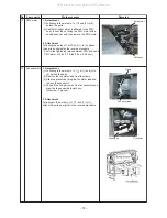
Page 69: ...CJ sensors from P C board CN100 TC1 3P Brown CN101 TC2 2P Black CN102 TCJ 2P Red Unlock the lock of the housing part and then remove the connectors 9 Remove the relay connector of the PMV lead 10 Remove body of the electric parts assembly M4 screw 1 2 Attachment Following step 1 of and 1 to 10 attach the parts as original in the reverse procedure Electric parts assembly Clamp Fan motor lead M4 scr...

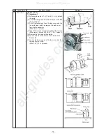
Page 70: ... gas pipe from the drain pan and then pull out it to the upper side 2 Attachment Following step 1 of and those in 1 to 11 attach the parts as original in the reverse procedure Drain pan assembly 1 Detachment 1 Following step 1 of and those in 1 to 11 detach the parts 2 Remove the drain pan assembly 2 Attachment Following step 1 in and those in 1 to 2 attach the parts as original in the reverse pro...

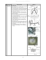
Page 71: ...e fixing screws of the fan motor and then remove the fan motor M4 x 0 47 12L 2 pieces 2 Attachment Following step 1 of and 1 to 5 attach the parts as original in the reverse procedure When attaching the Silocco fan meet the fixing screw for Silocco fan to the notch position on the shaft of the fan motor After fixing the fan case adjust the position of Silocco fan at the center of the fan case from...

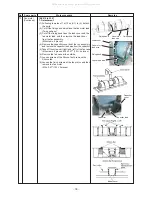
Page 72: ...1 position 2 Attachment Following step 1 of and 1 to 3 attach the parts as original in the reverse procedure Be sure to connect the capacitor lead to the specified position of the capacitor Capacitor installing leg Capacitor Connecting position of capacitor lead Capacitor lead wire Red Capacitor lead wire White All manuals and user guides at all guides com ...

Page 73: ...ke of the lead wire from the clamp of the electric parts box CN100 TC1 3P Brown CN101 TC2 2P Black CN102 TCJ 2P Red CN104 TA 2P Orange CN210 Fan motor 7P White CN104 PMV 6P Blue Remove the connectors by unlocking the locks of the housing part 8 Take off the fixing screws of the electric parts assembly fixing screws slide the electric parts assembly toward upper side and then remove it M4 screws 2 ...

Page 74: ...move the piping cover Left M4 screw 2 pieces 9 Remove the sensor lead and the PMV lead from the clamp 10 Remove the piping cover Right M4 screw 3 pieces 11 Take off the screws which fix the drain pan slide it toward right remove the drain pan from the side plate Left and then draw it toward you 12 Remove the dashboard of the heat exchanger M4 screw 4 pieces 13 Slide the heat exchanger toward right...

Page 75: ... PMV motor at 5 8 0 7 ft lbs 7 84 0 98 N m Fan assembly 1 Detachment 1 Following to the works in 1 of of 1 and 3 to 6 detach the parts 2 Remove the fan motor lead from the clamp 3 Slide the glass tube fixing the fan motor lead and remove the connector 4 Take off the fixing screws of the fan assembly and draw the fan assembly toward you M4 screw 2 pieces 2 Attachment Following to the works in 1 of ...

Page 76: ... from the fan assembly M4 screws 4 pieces 4 Take off the screws at right and left of the fan case M4 screws 4 pieces M4 x 0 47 12L 2 pieces 5 Remove the fan case at the outside 6 Loosen screws of the Silocco fan to remove the Silocco fan 7 Loosen the fixing screws of the fan motor and then remove the fan motor M4 x 0 47 12L 2 pieces Fan motor lead wire Lead cover Fixing band Grand lead wire Fixing...

Page 77: ...th lead and then fix them to the lead cover with the fixing band When attaching the fan motor reinforcement plate be careful to the screw hole position of the fan motor reinforcement plate When attaching the Silocco fan meet the fixing screw for Silocco fan to the notch position on the shaft of the fan motor After fixing the fan case adjust the position of Silocco fan at the center of the fan case...

Page 78: ...apacitor cover from the fan assembly and remove the capacitor lead wire from the capacitor 5 Take off the screws at right and left of the fan case M4 screws 8 pieces M4 x 0 47 12L 4 pieces 6 Remove the fan case at the outside 7 Loosen screws of the Silocco fan to remove the Silocco fan 8 Loosen the fixing screws of the fan motor and then remove the fan motor M4 x 0 47 12L 2 pieces Capacitor cover ...

Page 79: ...plate When attaching the Silocco fan meet the fixing screw for Silocco fan to the notch position on the shaft of the fan motor After fixing the fan case adjust the position of Silocco fan at the center of the fan case from side of the discharge port so that the Silocco fan does not hit to the fan case For the tightening torque of the screw fixing the Silocco fan control between 3 7 to 3 8 ft lbs 5...

Page 80: ...rocedure AP015 to 024 1 Detachment 1 Following to 1 of and 1 to 2 detach the parts M4 screw 2 pieces 2 Remove the capacitor M4 screw 1 position 2 Attachment Following to 1 of and 1 to 2 attach the parts as original in the reverse procedure AP007 to 024 Be sure to connect the capacitor lead to the specified position of the capacitor Capacitor cover Capacitor Capacitor lead Capacitor Capacitor insta...

Page 81: ...scribed below After completion of the work check the settings again including the indoor unit No and group header follower designation and confirm the integrity of the refrigerating cycle by conducting a test operation etc Replacement procedure Method 1 If it is possible to turn on the indoor unit and read the setting data from the P C board to be replaced via a wired remote control Reading EEPROM...

Page 82: ...the EEPROM location diagram section The old EEPROM supplied with the P C board to be replaced and now mounted on the service P C board needs to be replaced with the new EEPROM supplied with the service P C board Ø Replacing P C board and turning on power Procedure 2 Ø Writing EEPROM data in new EEPROM Procedure 3 Ø Resetting power supply applicable to all indoor units connected to remote control i...

Page 83: ... louvers swinging depending on the model 3 The button allows you to move the CODE No DN code up down by one place 4 First change the CODE No DN code from 10 to 01 To set filter sign lighting time Jot down the setting data displayed 5 Change the CODE No DN code using the button Again jot down the setting data displayed 6 Repeat step 5 until all the setting data has been jotted down See the CODE No ...

Page 84: ...the remote control Turn on the indoor unit using one of the methods described below according to the system configuration 1 Single stand alone operation Turn on the indoor unit and proceed to Procedure 3 2 Group operation A If it is possible to selectively turn on the indoor unit being serviced Turn on the indoor unit being serviced and proceed to Procedure 3 B If it is not possible to selectively...

Page 85: ... the CODE No list 6 Push the button The display should change from flashing to steady 7 Push the button to bring the system back to normal off state 5 Next write any setting changes made on site after installation such as address settings in the EEPROM Perform the tasks specified in step 1 again 6 Use the button to set the CODE No DN code to 01 01 01 01 01 To set filter sign lighting time 7 Check ...

Page 86: ...Indoor unit capacity See below table Refrigerant line address Indoor unit address Group address Automatic restart from power cut Option input selection CN080 Thermostat output selection T10 Input selection T10 Sensor selection Timer set Wired remote control 0001 150 hour 0000 Standard 0099 Unfixed 0000 No shift 0000 Standard 0000 Heat pump Depending on model type According to capacity type 0099 Un...

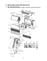
Page 87: ... 87 11 EXPLODED VIEWS AND PARTS LIST 11 1 Floor Console Exposed Type MML AP0074H2UL AP0094H2UL AP0124H2UL AP0154H2UL AP0184H2UL AP0244H2UL All manuals and user guides at all guides com ...

Page 88: ...R PMV EDM MD12TF 3 BODY PMV EFM 40YGTF VALVE PMV EDM B25YGTF 3 FAN MULTI BLADE FAN MULTI BLADE AIR FILTER COVER CONTROL PANEL WHITE GUARD FAN REFRIGERATION CYCLE ASSY REFRIGERATION CYCLE ASSY REFRIGERATION CYCLE ASSY REFRIGERATION CYCLE ASSY REFRIGERATION CYCLE ASSY SOCKET 3 8 IN SOCKET 1 4 IN NUT FLARE 1 2 IN NUT FLARE 5 8 IN SOCKET 1 2 IN SOCKET 5 8 IN GRILLE WHITE GRILLE HOSE DRAIN COVER WIRE L...

Page 89: ...R SERVICE TA SENSOR ASSY SERVICE TG F4 TC1 TRANSFORMER TT 12 TERMINAL BLOCK 2P 20A TERMINAL 4P P C BOARD ASSY MCC 1403 P C BOARD ASSEMBLY MCC 1520 Q ty Set MML AP 0074 H2UL 2 1 1 1 1 1 1 1 0094 H2UL 2 1 1 1 1 1 1 1 0124 H2UL 2 1 1 1 1 1 1 1 0154 H2UL 2 1 1 1 1 1 1 1 0184 H2UL 2 1 1 1 1 1 1 1 0244 H2UL 2 1 1 1 1 1 1 1 Electrical parts All manuals and user guides at all guides com ...

Page 90: ... 90 11 2 Floor Console Recessed Type MML AP0074BH2UL AP0094BH2UL AP0124BH2UL All manuals and user guides at all guides com ...

Page 91: ...NTROLLER SX TB01UE REMOTE CONTROLLER REFRIGERATION CYCLE ASSY CAPACITOR 1 5MFD 450V MOTOR FAN SWA 200U19A4B MOTOR PMV EDM MD12TF 3 VALVE PMV EDM B25YGTF 3 FAN MULTI BLADE FILTER CATCH DRAIN GUARD WIRE SOCKET 3 8 IN SOCKET 1 4 IN PLATE WIND HOSE ASSY PLATE ASSY CONDUIT COVER ASSY LABEL CAUTION LABEL WARNING HOLDER SENSOR TS BONNET NUT FLARE 1 4 IN BONNET HOLDER SENSOR NUT FLARE 3 8 IN BAND MOTOR LE...

Page 92: ...OR ASSY SERVICE TC F6 TC2 TCJ SENS0R SERVICE TA SENSOR ASSY SERVICE TG F4 TC1 TRANSFORMER TT 12 TERMINAL BLOCK 2P 20A TERMINAL 4P PC BOARD ASSY MCC 1403 P C BOARD ASSEMBLY MCC 1520 Q ty Set MML AP AP0074 BH2UL 2 1 1 1 1 1 1 1 AP0094 BH2UL 2 1 1 1 1 1 1 1 AP0124 BH2UL 2 1 1 1 1 1 1 1 Electrical parts All manuals and user guides at all guides com ...

Page 93: ... 93 MML AP0154BH2UL AP0184BH2UL AP0244BH2UL All manuals and user guides at all guides com ...

Page 94: ...ER SX TB01UE REMOTE CONTROLLER REFRIGERATION CYCLE ASSY REFRIGERATION CYCLE ASSY CAPACITOR 2 5MFD 400V CAPACITOR 450V 1MF MOTOR FAN AF 200 70 4KU MOTOR PMV EDM MD12TF 3 BODY PMV EFM 40YGTF FAN MULTI BLADE FILTER CATCH DRAIN GUARD WIRE SOCKET 3 8 IN SOCKET 1 4 IN NUT FLARE 1 2 IN NUT FLARE 5 8 IN SOCKET 1 2 IN SOCKET 5 8 IN HOSE ASSY PLATE ASSY CONDUIT COVER ASSY LABEL CAUTION LABEL WARNING HOLDER ...

Page 95: ... Description SENSOR ASSY SERVICE TC F6 TC2 TCJ SENS0R SERVICE TA SENSOR ASSY SERVICE TG F4 TC1 TRANSFORMER TT 12 TERMINAL BLOCK 2P 20A TERMINAL 4P PC BOARD ASSY MCC 1403 P C BOARD ASSEMBLY MCC 1520 Q ty Set MML AP AP0154 BH2UL 2 1 1 1 1 1 1 1 AP0184 BH2UL 2 1 1 1 1 1 1 1 AP0244 BH2UL 2 1 1 1 1 1 1 1 All manuals and user guides at all guides com ...

Page 96: ...tallation of multi air conditioner systems is on the increase because of the need for effective use of floor space individual control energy conservation by curtailing heat and carrying power etc Most importantly the multi air conditioner system is able to replenish a large amount of refrigerant compared with conventional individual air conditioners If a single unit of the multi conditioner system...

Page 97: ...ATION ALL Rights Reserved Revision record First issue Mar 2016 Revision 1 English was corrected Page 3 4 5 6 10 11 12 13 14 15 19 20 21 22 23 24 32 36 37 38 40 42 43 46 47 48 50 58 69 70 71 72 Jun 2016 Revision 2 The contents change of Description of service parts Jun 2017 Page 89 92 95 All manuals and user guides at all guides com ...

Reviews: