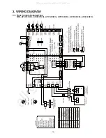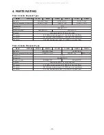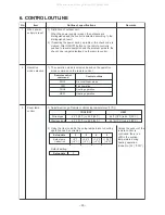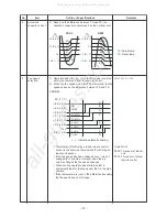
– 26 –
7. APPLIED CONTROL AND FUNCTION
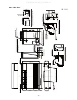
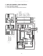
7-1. Indoor Control Block Diagram
7-1-1. When Main (Simple) Wired Remote Control Connected
DC5V
DC5V
CN2
CN1
DC5V
EEPROM
CPU
CPU
DC5V
DC12V
DC20V
AB
AB
AB
U2
U1
L2
L1
U2
U1
HA
U1
U2
L1
L2
L1
L2
U1
U2
EEPROM
Schedule Timer (Weekly timer mode)
Main (sub) remote control (up to 2 units)
Power
supply
circuit
Function setting
Key switch
Remote control
communication circuit
Display
LCD
Display
LED
Rechargeable
battery
LCD
driver
Display
LCD
Function setting
Key switch
Power
supply
circuit
*3
Outdoor
unit
Outdoor
unit
Power
source
Power
source
#2
#3
Sameas left
*2
Sameas left
*2
Up to 8 units can
be connected. *1
*1
Only up to 7 units if a
network adaptor is
installed with 2 main
(sub) remote control
connected.
*2 The
network
adaptor can
only be
installed in one
unit.
*3
A
weekly timer
cannot be
connected to a
sub remote
control.
Indoor/outdoor communication
Network adaptor : "1:1 model" connection interface
TCB-PCNT31TLUL
Outdoor
unit
Indoor unit
Main remote control
:RBC-AMT32UL
Sub remote control
:RBC-AS41UL
#1
Network adaptor (optional)
Switch setting
Power supply circuit
“1:1 Model”
Connection
Interface
Remote control
communication
circuit
T
ransformer
CPU
Indoor control P
.C. board (MCC-1403)
PMV
Louver
motor
Indoor
fan
motor
Power supply circuit
Driver
Remote
control
communication
circuit
T
A
sensor
TC2 sensor
TC1 sensor
TCJ sensor
CPU
H8/3039
In operation
Alarm
Getting ready
Thermostat ON
COOL
HEA
T
FA
N
AC
synchronization
signal input circuit
BUS
communication
circuit
External
output
T
ransformer
Fan motor
control circuit
Power source
208/230-1-60
All manuals and user guides at all-guides.com
all-guides.com

