


31
7
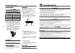
INDOOR UNIT FIXING
1. Pass the pipe through the hole in the wall, and hook the
indoor unit on the installation plate at the upper hooks.
2. Swing the indoor unit to right and left to confirm that it is
firmly hooked up on the installation plate.
3. While pushing the indoor unit onto the wall, hook it at the
lower part on the installation plate.
Pull the indoor unit toward you to confirm that it is firmly
hooked up on the installation plate.
• For detaching the indoor unit from the installation plate,
pull the indoor unit toward you while pushing its bottom up
at the specified parts.
8
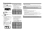
DRAINAGE
1. Run the drain hose sloped downwards.
NOTE
• Hole should be made at a slight downward slant on the
outdoor side.
2. Put water in the drain pan and make sure that the water
is drained out of doors.
3. When connecting extension drain hose, insulate the
connecting part of extension drain hose with shield pipe.
CAUTION
Arrange the drain pipe for proper drainage from the unit.
Improper drainage can result in dew-dropping.
This air conditioner has the structure designed to drain
water collected from dew, which forms on the back of the
indoor unit, to the drain pan.
Therefore, do not store the power cord and other parts at a
height above the drain guide.
1
2
Hook here
Installation plate
Hook
Push
(unhook)
Push
Push
Screw
Screw
Shield pipe
Drain hose
Space for pipes
Wall
Inside the room
Extension drain hose
Drain guide
Do not rise
the drain hose.
Do not put
the drain hose end
into water.
50 mm
or more
Do not put
the drain hose end
in the drainage ditch.
Do not form the drain hose
into a wavy shape.
REQUIREMENT
The lower part of indoor unit may float, due to thecondition of
piping and you cannot fix it to theinstallation plate. In that case,
use the screwsprovided to fix the unit and the installation plate.
Especially when the pipes are pulled out fromthe left side,
the unit must be screwed to the installation plate.
9
REFRIGERANT PIPING
n
Refrigerant Piping
1. Use copper pipe with 0.8 mm or more
thickness. (In case pipe size is dia. 15.9, with
1.0mm or more.)
2. Flare nut and flare works are also different
from those of the conventional refrigerant.
Take out the flare nut attached to the main
unit of the air conditioner, and use it.
REQUIREMENT
When the refrigerant pipe is long, provide support
brackets at intervals of 2.5 to 3m to clamp the refrig-
erant pipe.
Otherwise, abnormal sound may be generated.
CAUTION
IMPORTANT 4 POINTS FOR PIPING WORK
1. Remove dust and moisture from the inside of the
connecting pipes.
2. Tight connection (between pipes and unit)
3. Evacuate the air in the connecting pipes using
VACUUM PUMP.
4. Check the gas leakage. (Connected points)
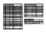
n
Pipe size
(dia : mm)
n
Permissible Piping Length and
Height Difference
They vary according to the outdoor unit.
For details, refer to the Installation Manual
attached to the outdoor unit.
Flaring
• Cut the pipe with a pipe cutter. Remove burrs
completely. Remaining burrs may cause gas
leakage.
• Insert a flare nut into the pipe, and flare the pipe.
As the flaring sizes of R410A differ from those
of refrigerant R22, the flare tools newly
manufactured for R410A are recommended.
However, the conventional tools can be used by
adjusting projection margin of the copper pipe.
u
Projection margin in flaring :
B (Unit : mm)
Rigid (Clutch type)
u
Flaring diam. meter size :
A (Unit : mm)
∗
In case of flaring for R410A with the conventional
flare tool, pull it out approx. 0.5 mm more than
that for R22 to adjust to the specified flare size.
The copper pipe gauge is useful for adjusting
projection margin size.
B
A
+0
-0.4
Outer dia. of copperpipe
6.4
9.5
12.7
15.9
A
R410A
9.1
13.2
16.6
19.7
MMK-
Gas side
Liquid side
AP007 to
AP012 type
9.5
6.4
AP015 to
AP018 type
12.7
6.4
AP024 type
15.9
9.5
Outer dia. of
copper pipe
6.4, 9.5
12.7, 15.9
R410A
tool used
R410A
0 to 0.5
Conventional
tool used
R410A
1.0 to 1.5