


The concealed high static pressure duct unit has 7 steps of static pressure (0.2-1.0 in. WG) adjustment to meet
the installation site requirements / conditions.
With these steps there are different speed fan taps associated to select correct air flow.
For meeting the site requirement / conditions, make sure the external static pressure and air flow are determined.
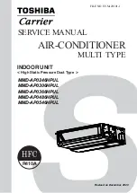
Plot the external static pressure and air flow on the below graph to determine the right speed fan step setting.
For example : Job site requirement is to deliver 870 CFM at 0.56 in. WG external static pressure. Using the below
graph, external static pressure on vertical axis and air flow on horizontal axis, the star mark indicates the job site
requirement.
The star mark is below 0.8 in. WG high speed fan tap line, which means the unit needs to be set to 0.8 in WG
external static pressure with high speed fan tap.
Please follow the process described in application controls of this manual for set up external static pressure.
Air flow rate (CFM)
0.00
0.10
0.20
0.30
0.40
0.50
0.60
0.70
0.80
0.90
1.00
1.10
1.20
1.30
100
300
500
700
900
1100
1300
1500
1700
Standard air flow: 706 CFM
High tap
1.0 in.WG-
0.8 in.WG- Mid tap
E
xt
ernal s
tat
ic
pres
su
re
(in.
W
G
)
AP0246 type
0.8 in.WG- Low tap
0.8
0.8 in.WG- High
0.6 in.WG- High tap
High tap
0.4 in.WG-
0.2
0.2 in.WG- High
★
NOTE
Supply air CFM will follow the solid line fan curve shown in the above graph if there is any change in the external
static pressure.
Supply air volume for medium and low fan speed tap is also set by remote controller. It will follow the dotted line
fan curve in the graph.
- 14 -