Roll Over Protection System (ROPS) Installation (continued)
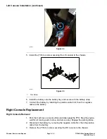
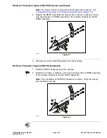
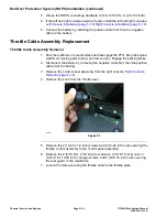
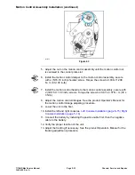
3. Torque the ROPS connecting hardware to 122–135.58 N • m (90–100 ft-lb).
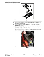
4. If the left and right consoles were removed, install the left and right consoles.
Left Console Installation (page 5–15) Right Console Installation (page 5–18)
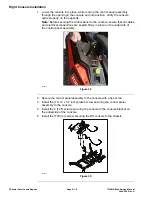
5. Connect the battery by installing the positive cable first, then the negative
cable to the battery.
Throttle Cable Assembly Replacement
Throttle Cable Assembly Removal
1. Park the machine on a level surface and disengage the PTO. Stop the engine,
wait for all moving parts to stop, and remove key. Engage the parking brake.
2. Disconnect the battery by removing the negative cable first, then the positive
cable from the battery.
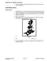
3. Remove the control panel assembly from the right console.
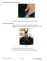
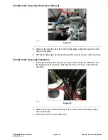
4. Remove the knob from the throttle lever.
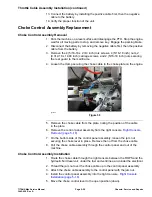
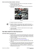
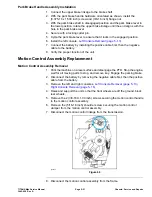
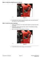
g336055
Figure 53
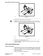
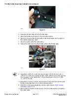
5. Remove the 2 (10-24 x 1/2 inch) screws and 2 (10-24 inch) nuts securing the
throttle control assembly to the control panel assembly.
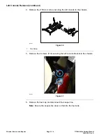
6. Remove the 4 (5/16-18 x 2 3/4 inch) torx screws, 4 (5/16-18 inch) nuts, 2
(0.312-18 x 1.000 inch) carriage screws, and 2 (5/16-18 inch) nuts securing
the rear guard to the mainframe.
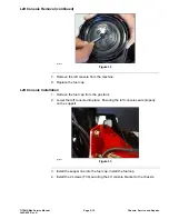
7. Loosen the clamp securing the throttle cable to the throttle plate.
Chassis: Service and Repairs
Page 5–26
TITAN® Max Service Manual
3442-428 Rev A
Summary of Contents for TITAN
Page 2: ...Revision History Revision History Page 2 TITAN Max Service Manual 3442 428 Rev A ...
Page 6: ...Preface Page 6 TITAN Max Service Manual 3442 428 Rev A ...
Page 26: ...Troubleshooting General Troubleshooting Page 3 6 TITAN Max Service Manual 3442 428 Rev A ...
Page 36: ...Engine Service and Repairs Page 4 10 TITAN Max Service Manual 3442 428 Rev A ...
Page 70: ...Chassis Service and Repairs Page 5 34 TITAN Max Service Manual 3442 428 Rev A ...
Page 92: ...Mower Deck Service and Repairs Page 6 22 TITAN Max Service Manual 3442 428 Rev A ...
Page 118: ...Electrical System Service and Repairs Page 8 18 TITAN Max Service Manual 3442 428 Rev A ...
Page 121: ... Drawing Rev A Sheet 1 3442 428 Rev A Page A 3 Kohler Engine Electrical Schematic g350654 ...

