background image

28

GTS 200

Compression

Part No.

19413

ÓÓ

ÓÓ

1

2

3

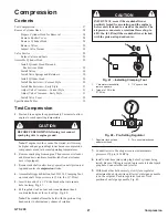
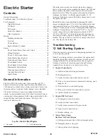
Fig. 49 – Setting Tester

1.

Inlet gauge set point

2.

Outlet gauge needle

3.

Regulator adjustment
knob

Note: Any air leaks at connections or fittings of tester will
affect the accuracy of test.

10. Listen for air leaking from cylinder head gasket, carburetor,

exhaust system and either crankcase breather or oil fill
dipstick tube.

Note: If a high flow of air is leaking from exhaust and
carburetor, make sure that piston is at TDC on
compression stroke.

Air flowing between cylinder and cylinder head
indicates that cylinder head gasket is leaking.

Air flowing from carburetor indicates air is leaking
past intake valve and seat.

Air flowing from exhaust system indicates air is
leaking past exhaust valve and seat.

Air flowing from crankcase breather tube or oil fill
dipstick tube indicates air is leaking past piston rings.

11. When test is complete, push regulator lock nut in and turn

regulator lock nut counterclockwise as far as it will go to
release pressure in combustion chamber.

12. Disconnect outlet hose from tester before removing from

spark plug hole.

Result

Reading is Green. A small
amount of air is leaking
from head gasket.

Replace head gasket,
then re-test.

Reading is Green
Minimum air leakage.

Look for other problems
that are not compression
related.

Reading is Green/Red or
Red, and all the air is leak-
ing from one component.

Look for a possible
problem with that
component.

Reading is Red, and air is
leaking from several com-
ponents.

Check that piston is at
TDC, on compression
stroke. If reading does not
change, look for problems
beginning with component
that appeared to leak the
most air. Re-test after re-
pair.

Remove Cylinder Head

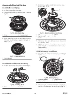
Prepare Cylinder Head for Removal

Before cylinder head can be removed external parts such as air
cleaner cover, fuel tank, oil fill tube and dipstick, blower
housing with rewind starter, muffler guard and muffler, air
cleaner, carburetor, carburetor control bracket assembly and
carburetor adapter or intake manifold must be removed.

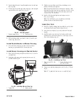
Remove Rocker Cover

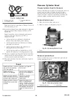
1. Remove four screws from rocker cover.

2. Remove rocker cover and gasket(s), Fig. 50.

1

1

Fig

.

 50 – Removing Rocker Cover

1.

Screw

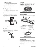
Remove Cylinder Head

Remove cylinder head screws, cylinder head, push rods and
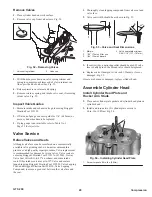
cylinder head gasket, Fig. 51.

1

2

Fig. 51 – Removing Cylinder Head

1.

Cylinder head screws

2.

Cylinder head

Summary of Contents for GTS 200

Page 1: ...L KEY KEYWAYS FLYWHEEL AND CRANKSHAFT INSTALL FLYWHEEL SPECIFICATIONS CARBURETION CARBURETOR IDENTIFICATION SERVICE CARBURETOR WALBRO LMS GOVERNOR CONTROLS CARBURETOR LINKAGE AND FLYWHEEL BRAKE REMOTE GOVERNOR CONTROLS FLYWHEEL BRAKE GOVERNOR ADJUSTMENTS GOVERNOR AND CARBURETOR LINKAGES GOVERNOR GENERAL INFORMATION GOVERNED RPM LIMITS MECHANICAL GOVERNOR COMPRESSION TEST COMPRESSION REMOVE CYLINDE...

Page 2: ...ON EXTENDED OIL FILL AND DIPSTICK BREATHER REMOVE BREATHER INSTALL BREATHER VALVE REMOVE OIL PUMP INSPECT OIL PUMP INSTALL OIL PUMP INSTALL PUMP COVER INSTALL OIL FILTER ADAPTER PISTONS RINGS AND RODS PISTON AND CONNECTING ROD SPECIFICATION TABLES CRANKSHAFT AND CAMSHAFT REMOVE CRANKSHAFT AND CAMSHAFT INSTALL CRANKSHAFT AND CAMSHAFT SPECIFICATION TABLES CYLINDER AND BEARINGS CYLINDER PLAIN OR DUTM...

Page 3: ...your service shop If you have questions or comments regarding this manual please contact us at the following address The Toro Company Consumer Service Department 8111 Lyndale Avenue South Bloomington MN 55420 1196 The Toro Company reserves the right to change product specifications or this manual without notice The Toro Company gratefully acknowledges the assistance of the Briggs Stratton Corporat...

Page 4: ...e Seat 20 Install Inlet Needle and Float 20 High Altitude Compensation 21 Install Carburetor 21 Install Air Cleaner 21 Governor Controls Carburetor Linkage and Flywheel Brake 22 Remote Governor Controls 22 Remote Control Wire Travel 22 Speed Regulation 22 Adjust Remote Controls 22 Flywheel Brake 22 Operation 22 Remove Flywheel Brake 23 Assemble Flywheel Brake 23 Brake Adjustment 24 Governor Adjust...

Page 5: ...ubrication 47 Extended Oil Fill and Dipstick 47 Breather 47 Remove Breather 47 Install Breather Valve 47 Remove Oil Pump 47 Inspect Oil Pump 48 Install Oil Pump 48 Install Pump Cover 48 Install Oil Filter Adapter 48 Pistons Rings and Rods 49 Piston and Connecting Rod 49 Remove Piston and Connecting Rod 49 Remove Piston Rings 49 Check Piston Ring Groove Wear 50 Check Piston Ring End Gap 50 Check Co...

Page 6: ...Nm Connecting rod 100 in lb 11 0Nm Crankcase cover or sump 110 in lb 12Nm Valve clearance Intake 004 008 in 0 10 0 20mm Exhaust 004 008 in 0 10 0 20mm Crankshaft Stroke 2 040 in 51 81mm Standard crankpin journal 1 0983 1 0991 in 27 897 27 917mm Journal reject sizes Magneto 878 in 22 30mm Crankpin 1 097 in 27 86mm PTO 1 065 in 27 05mm End play 002 033 in 0 05 0 84mm Engine RPM no load 3 000 RPM 150...

Page 7: ...m crankcase capacity is 26 ounces 0 78 Liter Use any high quality detergent oil having the American Petroleum Institute API service classification SF SG SH or SJ Before each use or every five hours ensure oil level is between ADD and FULL marks on dipstick Fig 1 Add oil if level is low 1 Position mower on level surface and clean around oil dipstick 2 Remove dipstick by rotating cap counterclockwis...

Page 8: ... oil fill tube and place a drain pan next to left side of mower 4 Tip mower on its left side allowing oil to drain into drain pan Fig 3 m 3848 1 2 Fig 3 1 Oil fill tube 2 Oil filter 5 If replacing the oil filter on models so equipped do so at this time 6 When oil is drained return mower to upright position and add fresh oil to engine Refer to Oil in this section Approximate Crankcase Oil Capacity ...

Page 9: ...EN A fire or explosion from gasoline can burn you and others and cause property damage HOW TO AVOID THE HAZARD Always place gasoline containers on the ground away from your vehicle before filling Do not fill gasoline containers inside a vehicle or on a truck or trailer bed because interior carpets or plastic truck bed liners may insulate the container and slow the loss of any static charge When pr...

Page 10: ...when mower is operated in dusty or dirty conditions Replace air cleaner parts if very dirty IMPORTANT Do not operate engine without air filter elements extreme engine wear or damage will occur Note Tipping mower on wrong side to service underside of mower may cause damage to air filters 1 Stop engine and pull wire off spark plug Fig 7 m 3662 1 2 Fig 7 Remove Spark Plug Wire Prior to Service 1 Prim...

Page 11: ... for damaged gaskets 7 Check governor linkage and springs for damage wear also check adjustment 8 Clean fuel tank and lines 9 Remove flywheel Check for oil seal leakage both flywheel and PTO sides Check flywheel key 10 Check armature coil Inspect all wires for breaks and or damaged insulation Be sure lead wires do not touch flywheel Check stop switch and lead s 11 Remove oil debris and nicks from ...

Page 12: ...uretion 18 Electric starter 12 V Blower housing Electric Starter 38 Breather and valve cover Lubrication 47 Valves and springs rocker arms push rods cylinder head and shields valve guides and seats Compression 27 Rewind starter Rewind Starter 33 Flywheel Ignition 14 Check crankshaft end play Crankshaft and Camshaft 53 Remove burrs from crankshaft extension Crankshaft and Camshaft 53 Crankcase cove...

Page 13: ... or sump Crankshaft and Camshaft 53 Breather Lubrication 47 Flywheel starter cup and fan Ignition 14 Ignition armature assembly Ignition 14 Adjust ignition armature to flywheel air gap Ignition 14 Check spark Ignition 14 Electric starter 12 V Electric Starter 38 Valves valve stem seals springs retainers rocker arms Compression 27 Cylinder head and push rods Compression 27 Adjust valve clearance Co...
Page 14: ... Ignition for additional information If spark does not occur look for 1 Shorted stop switch wire 2 Shorted stop switch 3 Ignition armature failure 4 Improperly operating interlock system Note If engine runs but misses during operation a quick check to determine if ignition is or is not at fault can be made by inserting the spark tester between the ignition cable and the spark plug A spark miss wil...

Page 15: ...e coupling Replace if coupling allows blade to shift causing unbalance 5 Mounting bolts loose Tighten 6 Mounting deck or plate cracked Repair or replace 7 Damaged belts or pulleys Power Loss 1 Grass cuttings build up under deck 2 No lubrication in transmission or gear box 3 Dull blade 4 Excessive drive belt tension may cause excess bearing wear or seizure Noise 1 BBC system problems if so equipped...

Page 16: ...G FLYWHEEL KICKBACK can occur if the flywheel key is sheared and bodily injury may occur Check Ignition 1 Connect spark plug wire to Spark Tester Fig 9 2 Operate starter and observe spark gap in tester If spark jumps tester gap ignition is good Note Flywheel must rotate at 350 RPM minimum Note Spark will be observed 2 1 Fig 9 Checking for Spark 1 Spark plug wire 2 Spark tester Briggs Stratton Tool...

Page 17: ...armature Fig 12 2 3 4 1 Fig 12 Removing Ignition Armature 1 Ignition armature 2 Screws 3 Stop switch wire 4 Terminal Remove Flywheel 1 Remove blower housing 2 Use flywheel holder to hold flywheel from turning Fig 13 1 Fig 13 Removing Flywheel Nut 1 Flywheel holder Briggs Stratton Tool 19372 3 Use socket and breaker bar to remove flywheel nut Note Remove ignition armature before removing flywheel 4...

Page 18: ...se a steel key under any circumstances WARNING DO NOT use impact wrenches to install flywheel 3 Install starter cup cooling fan and flywheel nut or screw 4 Use flywheel holder to hold flywheel from turning Fig 16 5 Install flywheel nut or screw 6 Use socket and torque wrench to tighten flywheel nut or screw 7 Torque as listed in Table No 1 Page 17 1 2 Fig 16 Torquing Flywheel 1 Briggs Stratton Too...

Page 19: ...e Table No 1 Page 17 for armature air gap Loosen mounting screw so magnet will pull armature down against thickness gauge 4 Torque both mounting screws to 25 in lbs 3 0Nm Rotate flywheel to remove thickness gauge 5 Install outer blower housing and screws and torque screws to 85 in lbs 10 0Nm Fig 19 1 1 Fig 19 Installing Outer Blower Housing 1 Torque screws to 85 in lbs Specifications Table No 1 Ar...

Page 20: ...oved fire can result CAUTION TO PREVENT accidental starting when servicing engine or equipment always remove spark plug wire from spark plug and prevent wire from contacting spark plug Service Carburetor Walbro LMS These carburetors have a fixed high speed main jet with non adjustable idle mixture Fig 21 2 1 1 1 3 4 5 6 Fig 21 Fixed Main Jet Carburetor 1 Float bowl 2 Choke plate 3 Choke lever 4 Th...

Page 21: ...tor control bracket 4 Gasket 5 Current style mounting hole 6 Early style 4 Remove two 2 carburetor mounting screws Disassemble Carburetor 1 Remove bowl nut with fixed main jet and fiber washer 2 Remove float bowl and bowl gasket from carburetor 3 Remove float hinge pin float and inlet needle Fig 24 1 2 3 Fig 24 Removing Main Jet Float Hinge Pin and Inlet Needle 1 Float 2 Float hinge pin 3 Inlet ne...

Page 22: ...nstalling Welch Plug 1 Welch plug 2 Pin punch 2 Press in until plug is flat Do not cave in plug 3 After plug is installed seal outside edge of plug with fingernail polish or non hardening sealant Install Throttle Shaft 1 Install throttle shaft and foam washer 2 Turn shaft until flat is facing out 3 Lay throttle plate on shaft with numbers facing out and install screw Fig 27 Use a new patchlock scr...

Page 23: ...n parts place carburetor on control bracket Fig 31 4 Install carburetor assembly with two 2 mounting screws torquing screws to 80 in lbs 10 0Nm Fig 31 1 1 1 2 3 4 5 6 Fig 31 Installing Carburetor 1 Mounting screw 2 Carburetor 3 Carburetor control bracket 4 Gasket 5 Current style mounting hole 6 Early style Install Air Cleaner 1 Install breather tube on air cleaner primer base and position base wit...

Page 24: ...ring to obtain desired engine speed Remote controls will provide governor control at all positions Speed Regulation When remote control is moved toward FAST position governor control rotates and increases tension of governor spring on governor lever Governor link moves throttle lever and valve on carburetor toward wide open position Fig 34 1 2 3 Fig 34 Speed Regulation air cleaner removed for clar...

Page 25: ...ke bracket and remove bracket Fig 38 1 3 4 5 6 7 8 2 Fig 38 Removing Brake Bracket 1 Stop switch wire 2 Screw 3 Anchor 4 Brake bracket 5 Starter interlock switch wires 6 Brake spring 7 Brake lever 8 Brake pad Inspect Flywheel Brake and Switches 1 Inspect brake lining on brake lever Replace brake assembly if lining is less than 090 2 28mm thick 2 Test stop switch as described in the section General...

Page 26: ...r to position pad closer to flywheel when handle control bail is in RUN position 4 Replace brake assembly if correct adjustment cannot be made Governor Adjustments To remove slack from the governor linkage 1 Slightly loosen the governor nut Fig 39 1 2 3 Fig 39 Adjusting Governor Linkage 1 Governor lever nut 2 Governor lever 3 Governor crank 2 Turn the governor crank to the right clockwise until it...

Page 27: ...n the engine is operated on a completely assembled machine The RPM should be measured with the mower on a hard surface to eliminate cutting load on the blade If a governor spring must be replaced consult the appropriate Toro Illustrated Parts List CAUTION AFTER A new governor spring is installed check engine top no load speed Run engine at half throttle to allow the engine to reach normal operatin...

Page 28: ...gasket s of same thickness as originally removed on cylinder 2 Place Seal Protector Briggs Stratton Tool 19334 or 19356 BROWN in seal of sump and slide sump down over crankshaft until sump seats Note It may be necessary to rotate crankshaft and cam gear to get oil pump to engage oil pump drive slot in cam gear on vertical crankshaft engines 3 Install crankcase cover or sump screws and torque screw...

Page 29: ...ad center of compression stroke 4 Assemble Briggs Stratton Tool 19314 Clamping Tool on crankshaft Torque screws to 150 in lbs 17 0Nm 5 Insert drive end of a 1 2 drive breaker bar into square hole in clamp Fig 47 6 Pull regulator lock nut out and turn adjustment knob counterclockwise as far as it will go Fig 48 Note The crankshaft must be held with the piston at top dead center to eliminate any cha...

Page 30: ...ore removing from spark plug hole Result Reading is Green A small amount of air is leaking from head gasket Replace head gasket then re test Reading is Green Minimum air leakage Look for other problems that are not compression related Reading is Green Red or Red and all the air is leak ing from one component Look for a possible problem with that component Reading is Red and air is leaking from sev...

Page 31: ...orn valves Valve seats are cut using Briggs Stratton Tool 19237 or 19343 Neway Valve Seat Cutter Kit to 45 on exhaust and some intake seats Other intake seats are cut to 30 Valve and seat are lapped in using Briggs Stratton Tool 19258 Valve Lapping Tool and Briggs Stratton Part 94150 Valve Lapping Compound to assure a good seal between the valve face and the seat 1 Thoroughly clean lapping compoun...

Page 32: ...t Continue to press until small end of slot can slide into groove on valve stem Be sure retainer is fully engaged in valve stem groove Fig 56 1 Fig 56 Installing Valve Retainers 1 Valve retainer Install Cylinder Head Note Do not use sealer of any kind on gaskets 1 Coat threads of cylinder head screws with Briggs Stratton Part 93963 Valve Guide Lubricant 2 Place new cylinder head gasket on cylinder...
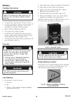
Page 33: ... revolutions to be sure push rods operate rocker arms Adjust Valve Clearance Current Style Note Check valve clearances while engine is cold 1 Turn crankshaft until piston is at Top Dead Center both valves closed on compression stroke 2 Insert a narrow screwdriver or small rod into spark plug hole against piston Screwdriver or rod is used to gauge piston movement 3 Turn crankshaft clockwise flywhee...

Page 34: ...4 Locking Jam Nut 1 Torque jam nut 85 in lbs 10Nm Install Valve Cover 1 Install valve cover with new gasket Install four screws and tighten screws to torque listed in Table No 5 Page 32 in sequence shown in Fig 65 2 Install carburetor exhaust manifold air guides shields and other parts removed from cylinder head 1 4 2 3 Fig 65 Valve Cover Torque Sequence Specification Tables Table No 1 Valve Guide...
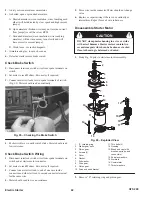
Page 35: ...iner Assembly 36 Wind Spring and Install Rope 36 Install Rewind Starter on Blower Housing 37 Install Blower Housing and Rewind Starter 37 Install Fuel Tank 37 General Information Fig 66 Rewind Starter Exploded View Remove Blower Housing and Starter 1 Remove cover screw and air cleaner cover Fig 67 ÔÔÔÔ ÔÔÔÔ ÔÔÔÔ m 3664 1 2 4 3 Fig 67 Removing Air Cleaner Cover 1 Knob 2 Cover 3 Foam pre cleaner 4 P...

Page 36: ... Remove four 4 screws two 2 from front and two 2 from rear of blower housing Fig 71 Note Rewind starters used on these engines are riveted to the blower housing Replacement starters are supplied with screws and nuts to replace the rivets for mounting starter 1 1 1 Fig 71 Removing Blower Housing 1 Screw Disassemble Rewind Starter Remove Rope 1 Pull starter rope out as far as it will go 2 While hold...

Page 37: ...e 2 Replace pulley if damaged or worn 3 Inspect spring for broken ends kinks and burrs Replace assembly if any of above conditions exists 4 Inspect starter housing for wear or sharp edges at rope eyelet center pivot post and inner spring anchor tab Fig 75 1 2 3 Fig 75 Inspecting Starter Housing 1 Inner spring anchor 2 Rope eyelet 3 Center pivot point 5 Replace assembly if worn or damaged CAUTION P...

Page 38: ... Posts 2 Pawls 2 Install retainer making sure that slots in retainer engage tabs on pulley Fig 79 1 2 3 4 Fig 79 Installing Retainer and Screw 1 Slot 2 Torque screw to 70 in lbs 8 0Nm 3 Retainer 4 Tab 3 Hold retainer down and install retainer screw Torque screw to 70 in lbs 8 0Nm 4 While holding retainer rotate pulley to extend and retract pawls If they do not extend and retract remove retainer an...

Page 39: ...nstall three remaining screws Install oil fill tube and dipstick Note Install fuel tank bracket with blower housing After torquing blower housing screws install one 1 screw at top of fuel tank bracket to top of blower housing and torque screw to 85 in lbs 10 0Nm 4 Install oil fill tube and dipstick and torque screw to 45 in lbs 5 0Nm Note The oil fill tube screw is installed on fuel tank bracket t...

Page 40: ...inutes of running to replace the battery charge used to start the engine one time Should the battery need additional recharging the trickle charger is plugged into a 120 volt AC household outlet and then connected to battery The battery will be fully charged within a 72 hour period It is not recommended that battery be recharged if temperatures are below 40 F 4 C For best results charge battery wi...

Page 41: ...86 DC Shunt Tachometer A Trysit Sirometer Tachometer is available from your Briggs Stratton source of supply Use Briggs Stratton Tool 19200 The Sirometer measures from 800 to 25 000 revolutions per minute RPM Fig 87 Fig 87 Trysit Sirometer Tachometer Starter Test Bracket A starter motor test bracket may be made as shown in Fig 88 2 1 4 57mm 3 1 2 89mm 2 51mm 10 254mm 1 25mm 3 1 2 89mm 4 102mm 1 2 ...

Page 42: ...st 15 minutes Internal Contact Drink tap water milk or milk of magnesia Take whites of eggs Do not induce vomiting WARNING IN CASE of external or internal contact call a physician immediately Check Battery 1 Physical check clean if necessary A Corrosion B Dirt C Terminal clean undamaged Replace if damaged with Toro Part 49 8141 2 Fully charge battery with charger supplied with the mower 3 Install ...

Page 43: ... systems used with the GTS 200 engine Fig 93 Typical Wiring Diagrams for Toro Walk Behind Mowers Check 12 Volt Starter Motor A performance test of starter motor may be made in the following manner CAUTION GROUND SPARK plug wire using Briggs Stratton Tool 19051 or 19368 Ignition Tester before doing this test Do not engage starter motor more than five seconds 1 Set multimeter to read DC amps Multime...

Page 44: ...erlock switch wires from spade terminals on switch and at starter motor connector 2 Set meter to read Ω ohms Zero meter if required 3 Connect one meter test lead to end of one wire inside connector and other test lead to second connector terminal for the same wire 4 Meter should read low or no resistance 5 Move wire inside connector Meter should not change value 6 Replace or repair wiring if there...

Page 45: ... bearings and armature should not be soaked in a solvent 3 Armature commutator may be cleaned with a fine sandpaper or commutator paper Note Do not use any metallic oxide paper or emery cloth as metallic oxide or emery will become embedded in commutator causing rapid brush wear 4 If armature is suspected to be defective a new armature should be tried in motor 5 If proper testing equipment is avail...

Page 46: ...etween armature and drive end head to obtain end play 13 Slip pinion and starter motor clutch gear on shaft 14 Add approximately 3 4 ounce of Briggs Stratton Part 100060 grease under large gear and on gear teeth 15 Oil felt washer with electric motor oil 16 Install washer gasket and cover Fig 102 1 1 2 Fig 102 Lubricating Gears 1 Apply lubricant here 2 Oil felt washer 17 Tap end cap edge lightly u...

Page 47: ...ose pinched or corroded battery charge leads Open shorted or grounded wires be tween output connector and battery Damaged battery shorted battery cells Damaged alternator magnets Defective stator Equipment to Test Alternators The following equipment is recommended to test and repair alternators Digital Multimeter Use a Digital Multimeter The meter may be used to read volts ohms or amperes and test...

Page 48: ... stator air gap is within specification and there is low or no output replace stator Install Stator Studs If stator studs were removed install and torque to 30 in lbs 3 4Nm Fig 109 Adjust Stator Air Gap 1 Stator air gap is 0 010 25mm 2 Rotate flywheel until magnets are away from stator 3 Loosen both stator mounting screws and move stator away from flywheel and tighten one screw 4 Place a 0 010 25m...

Page 49: ...kage past piston rings valve guides oil seals governor lever shaft and gaskets Remove Breather 1 Before breather can be removed remove fuel tank extended oil fill tube blower housing flywheel and muffler 2 Remove two screws holding breather to cylinder Fig 111 3 Remove four screws holding breather passage cover and gasket Fig 111 2 1 1 3 Fig 111 Removing Breather and Breather Passage Cover 1 Gaske...

Page 50: ... Oil and install inner rotor in pump cavity 3 Turn rotors to engage pump in cam or governor gear 4 Place O ring in groove in cover Fig 114 5 4 3 2 1 Fig 114 Installing Oil Pump 1 Outer rotor 2 Groove 3 Cover 4 O ring 5 Inner rotor Install Pump Cover on models so equipped 1 Install O ring in groove in sump Fig 115 Fig 115 Installing Pump Cover 2 Place pump cover on oil pump cavity and install three...

Page 51: ... Remove connecting rod cap Fig 117 1 Fig 117 Remove Piston and Connecting Rod 1 Box wrench to remove screws 2 Remove any carbon or ridge at top of cylinder bore to prevent ring breakage 3 Push piston and rod out through top of cylinder Note The GTS 200 engine uses oil drain slots in ring lands Fig 118 1 Fig 118 Oil Control Slots 1 Drain slot Remove Piston Rings Remove piston rings using Briggs Str...

Page 52: ...ce on crankshaft Reject sizes of crankpin bearing hole and piston pin bearing hole Fig 122 are shown in Table No 3 page 52 2 1 Fig 122 Checking Rod Bearings 1 Crankpin bearing 2 Piston pin bearing Check Piston Pin and Piston Pin Bore If piston pin is worn 0005 013mm out of round or below reject size shown in Table 4 it should be replaced If piston pin bore Fig 123 is worn over reject size replace ...

Page 53: ...ad of piston is even with edge of compressor 4 Tighten compressor until piston cannot be turned in compressor 5 Then loosen compressor until piston can be turned with slight resistance Note Do not attempt to install piston and ring assembly without ring compressor Install Connecting Rod and Piston 1 Thoroughly clean and then oil cylinder bore 2 Rotate crankshaft until crankpin journal is at bottom...

Page 54: ...d rods causing scoring 8 Rotate crankshaft two 2 revolutions to make sure crankpin and rod are not binding during rotation 9 Move connecting rod sideways to be sure rod slides from side to side Specification Tables Table No 1 Piston Ring Groove Rejects Compression Rings Oil Control Ring 007 18mm 007 18mm Table No 2 Piston Ring End Gap Reject Top Comp Ring Center Comp Ring Oil Control Ring 020 51mm...

Page 55: ...ft from resting on workbench 6 Rotate crankshaft until timing marks are aligned 7 With camshaft in this position the valve tappets will remain clear of cam lobes Lift out camshaft Fig 131 3 2 1 2 Fig 131 Removing Camshaft 1 Timing gear 2 Timing mark 3 Camshaft Remove Crankshaft 1 Before crankshaft can be removed it is necessary to remove flywheel page 15 and connecting rod cap page 49 2 Rotate cra...

Page 56: ...ector into magneto seal 4 Supporting both ends of crankshaft install in cylinder 5 Install connecting rod on crankshaft page 51 6 Install slip fit timing gear if removed with inner chamfer toward crankpin This assures timing mark will be visible Install Camshaft Install camshaft making sure tappets clear cam lobes Timing marks must align Fig 135 1 1 1 Fig 135 Aligning Timing Marks Vertical Cranksh...

Page 57: ... Journal Crankpin Journal PTO Journal Eccentric 873 22 17mm 1 097 27 86mm 1 060 26 92mm Table No 2 Crankshaft Grinding Dimensions for Undersize Connecting Rods 020 51 mm Undersized Crankpin Size Fillet Radius Crankshaft Throw 1 0783 1 0791 27 389mm 27 409mm 069 079 1 75mm 2 01mm 1 020 25 908mm Table No 3 Camshaft Reject Sizes Mag Journal PTO Journal Cam Lobes 498 498 Galled 498 12 65mm 498 12 65mm...

Page 58: ...le in the cylinder bore Note When installing new piston rings in a cylinder bore that is within specification shown the cylinder bore should be reconditioned The proper cylinder cross hatch ensures proper ring lubrication and break in Some engine models produced at the factory have diamond bored cylinders which do not exhibit a cross hatch finish The diamond bore cylinders are reconditioned using ...

Page 59: ...d to repair magneto bearing from Table No 1 Remove and discard oil seal for bearing to be repaired Place pilot guide bushing in bearing opposite of bearing to be repaired Have flange of bushing on inside of crankcase Replace sump if sump crankshaft bearing is worn or damaged Table No 1 Magneto Bearing Repair Tool Chart Briggs Stratton Tools Cylinder Support Bushing Driver Plug Gauge 19123 19124 19...

Page 60: ...alling crankcase cover or sump Do not force cover or sump Make sure mechanical governor gear and oil pump when used is engaged with cam gear 1 For adjustment procedure for crankshaft end play see Crankshaft and Camshaft page 55 2 Torque crankcase cover screws in sequence shown in Fig 146 1 2 3 4 5 6 7 Fig 146 Torque Sequence Specification Tables Table No 3 Seal Protectors Briggs Stratton Tool Colo...

Page 61: ...and rewind starter Fig 149 1 1 2 3 Fig 149 Removing Dipstick and Oil Fill Tube Blower Housing and Rewind Starter 1 Screws 4 2 Blower housing and rewind starter 3 Dipstick and oil fill tube 5 Remove two screws holding exhaust pipe flange to cylinder head one 1 screw holding muffler bracket to cylinder head and one 1 screw holding muffler to cylinder and remove muffler assembly Fig 150 6 Remove old ...

Page 62: ...torque to 85 in lbs 10 0Nm Fig 151 5 Install screw in muffler to cylinder bracket and torque to 85 in lbs 10 0Nm Install Muffler Guard 1 Lightly coat muffler guard mounting screws with Valve Guide Lubricant Briggs Stratton Part 93963 2 Place muffler guard over muffler and torque muffler guard to bracket screw to 85 in lbs 10 0Nm Fig 148 3 Torque muffler guard to cylinder screw to 50 in lbs 6 0Nm 4...

Reviews: