Toro 22306 Operator'S Manual Download Page 32

1. Lower the loader arms, stop the engine, and

remove the key.

2. Syphon the gasoline from the tank using a

pump type syphon.

Note:

Now is the best time to install a new fuel

filter because the fuel tank is empty.

Electrical System

Maintenance

Servicing the Battery

Warning

CALIFORNIA

Proposition 65 Warning

Battery posts, terminals, and related
accessories contain lead and lead
compounds, chemicals known to the State of
California to cause cancer and reproductive
harm. Wash hands after handling.

Important:

The following procedures

apply when servicing a (dry) battery that has
replaced the original battery. The original
(wet) battery does not require service.

Check the electrolyte level in the battery every 100
hours. Always keep the battery clean and fully
charged. Use a paper towel to clean the battery
case. If the battery terminals are corroded, clean
them with a solution of four parts water and one
part baking soda. Apply a light coating of grease
to the battery terminals to reduce corrosion.

Voltage: 12 v, 450 Cold Cranking Amps

Checking the Electrolyte Level

1. Stop the engine and remove the key.

2. Remove the 4 bolts securing the battery cover

and remove it from over the battery.

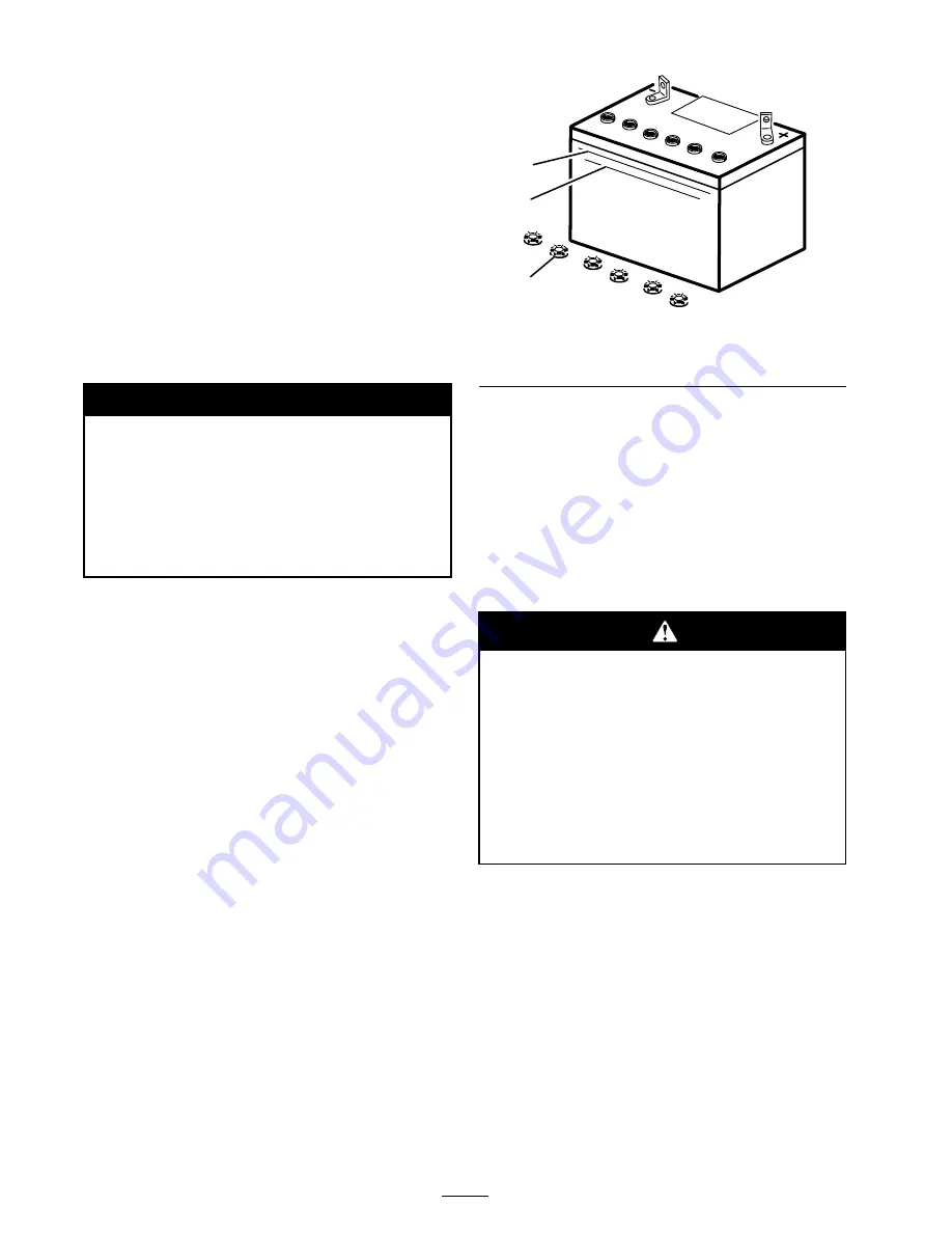
3. Look at the side of the battery. The electrolyte

must be up to the Upper line (Figure 34).
Do not allow the electrolyte to fall below the
Lower line (Figure 34).

2
3

1

G003794

Figure 34

1. Filler caps

3. Lower line

2. Upper line

4. If the electrolyte is low, add the required

amount of distilled water; refer to Adding
Water to the Battery.

Adding Water to the Battery

The best time to add distilled water to the battery
is just before you operate the traction unit. This
lets the water mix thoroughly with the electrolyte
solution.

Battery electrolyte contains sulfuric acid
which is a deadly poison and causes severe
burns.

Do not drink electrolyte and avoid
contact with skin, eyes or clothing. Wear
safety glasses to shield your eyes and
rubber gloves to protect your hands.

Fill the battery where clean water is
always available for flushing the skin.

1. Remove the battery from the traction unit.

Important:

Never fill the battery with

distilled water while the battery is installed
in the traction unit. Electrolyte could be
spilled on other parts and cause corrosion.

2. Clean the top of the battery with a paper towel.

3. Remove the filler caps from the battery

(Figure 34).

4. Slowly pour distilled water into each battery

cell until the electrolyte level is up to the Upper
line (Figure 34) on the battery case.

32

Summary of Contents for 22306

Page 1: ...3354 650 Rev B Dingo TX 420 and TX 425 Compact Utility Loader Model No 22306 Serial No 260000001 and Up Model No 22307 Serial No 260000001 and Up Register your product at www Toro com Original Instruc...

Page 2: ...y Replacements may be ordered through the engine manufacturer Introduction Read this information carefully to learn how to operate and maintain your product properly and to avoid injury and product da...

Page 3: ...the Rear Access Cover 26 Removing the Side Screens 26 Installing the Side Screens 26 Removing the Front Screen 26 Lubrication 27 Greasing the Traction Unit 27 Engine Maintenance 28 Servicing the Air C...

Page 4: ...hat safety glasses long pants safety shoes and hearing protection Long hair loose clothing or jewelry may get tangled in moving parts Inspect the area where the equipment is to be used and remove all...

Page 5: ...e there is suf cient clearance for the operator to safely maneuver the product Before digging have the area marked for underground utilities and do not dig in marked areas Locate the pinch point areas...

Page 6: ...efore connecting or disconnecting it from the battery Wear protective clothing and use insulated tools Keep all parts in good working condition and all hardware tightened Replace all worn or damaged d...

Page 7: ...ardboard or paper to nd hydraulic leaks never use your hands Hydraulic uid escaping under pressure can penetrate skin and cause injury requiring surgery within a few hours by a quali ed surgeon or gan...

Page 8: ...Slope Chart 8...

Page 9: ...Safety decals and instructions are easily visible to the operator and are located near any area of potential danger Replace any decal that is damaged or lost 108 4658 1 Operator s Manual location 2 F...

Page 10: ...WEAR SHOULD BE WORN WHEN CONNECTING COUPLERS HYDRAULIC COUPLERS MAY BE HOT PROTECTIVE WEAR SHOULD BE WORN WHEN CONNECTING COUPLERS HYDRAULIC COUPLERS MAY BE HOT PROTECTIVE WEAR SHOULD BE WORN WHEN CON...

Page 11: ...108 4670 108 4671 93 9084 1 Lift point 2 Tie down point 11...

Page 12: ...o not overcharge the battery 1 2 3 4 G003792 Figure 2 1 Positive post 3 Charger red wire 2 Negative post 4 Charger black wire Charging the battery produces gasses that can explode Never smoke near the...

Page 13: ...has three positions off run and start To start the engine rotate the key to the start position Release the key when engine starts and it will move automatically to the run position To stop the engine...

Page 14: ...attachments such as the leveler and the hydraulic blade to follow the contours of the ground i e oat when grading Figure 6 1 Lower the loader arms 4 Tilt the attachment forward 2 Raise the loader arm...

Page 15: ...top the engine and allow the traction unit to cool Hour Meter Tachometer When the engine is off the hour meter tachometer displays the number of hours of operation that have been logged on the tractio...

Page 16: ...43 inches 109 cm Weight 2060 lb 935 Kg Operating capacity 500 lb 227 Kg Tipping capacity 1530 lb 694 Kg Wheelbase 31 2 inches 79 cm Dump height with narrow bucket 47 inches 119 cm Reach fully raised w...

Page 17: ...of B a Rear Uphill rating of D and a Side Uphill rating of C then you could drive forward up a 205 slope rearward up a 125 slope or sideways on a 145 slope as listed in the following table for the TX...

Page 18: ...c electricity can be released causing a spark which can ignite the gasoline vapors A re or explosion from gasoline can burn you and others and can damage property Always place gasoline containers on t...

Page 19: ...9 6 Slide the dipstick fully into the dipstick tube Figure 9 7 Pull the dipstick out and look at the metal end 8 If the oil level is low clean around the oil ller cap and remove the cap Figure 10 Figu...

Page 20: ...near freezing or lower hydraulic system damage could occur When starting the engine in cold conditions allow the engine to run in the middle throttle position for 2 to 5 minutes before moving the thr...

Page 21: ...Remove the hairpin cotter and clevis pin securing the cylinder lock to the loader arm Figure 13 Figure 13 1 Cylinder lock 3 Clevis pin 2 Lift cylinder 4 Hairpin cotter 5 Lower the cylinder lock over...

Page 22: ...with enough space behind it to accommodate the traction unit 2 Start the engine 3 Tilt the attachment mount plate forward 4 Position mount plate into the upper lip of the attachment receiver plate Fig...

Page 23: ...omponents Do not touch hydraulic uid spills 7 Push the attachment female connector into the male connector on the traction unit 8 Con rm that the connection is secure by pulling on the hoses 9 Move th...

Page 24: ...k and adjust the track tension Check the hydraulic lines for leaks loose ttings kinked lines loose mounting supports wear weather and chemical deterioration Check for dirt build up in the chassis Ever...

Page 25: ...llow the engine to cool before opening any covers Opening the Hood 1 Turn the hood latch clockwise Figure 16 Figure 16 1 Hood 2 Hood latch 2 Swing the hood up Figure 16 3 Swing the prop rod up and sec...

Page 26: ...slots in the front screen and frame Figure 19 1 Side screen Installing the Side Screens Slide the side screens into place in the slots in the front screen and frame Removing the Front Screen If the en...

Page 27: ...previously 10 Slide the heat shield between the frame and the front weight and secure it to the front screen grill using the carriage bolts and nuts removed previously Figure 20 11 Tighten the bolts s...

Page 28: ...from getting into the engine and causing damage 4 Unscrew the knob and remove the air cleaner cover Figure 25 Figure 25 1 Knob 6 Foam pre lter 2 Air cleaner cover 7 Paper lter 3 Cover nut 8 Rubber se...

Page 29: ...m 4 Install the air cleaner cover and secure with the knob Figure 25 5 Close the hood Servicing the Engine Oil Change oil after the rst 50 operating hours and then every 100 operating hours thereafte...

Page 30: ...in coat of new oil to the rubber gasket on the replacement lter 7 Install the replacement oil lter to the lter adapter Turn the oil lter clockwise until the rubber gasket contacts the lter adapter the...

Page 31: ...fuel lter Figure 33 Figure 33 1 Filter 2 Hose clamp 5 Squeeze the ends of the hose clamps together and slide them away from the lter Figure 33 6 Place a drain pan under the fuel lines to catch any le...

Page 32: ...cover and remove it from over the battery 3 Look at the side of the battery The electrolyte must be up to the Upper line Figure 34 Do not allow the electrolyte to fall below the Lower line Figure 34 2...

Page 33: ...post 3 Red charger lead 2 Negative battery post 4 Black charger lead 4 When the battery is fully charged unplug the charger from the electrical outlet then disconnect the charger leads from the batter...

Page 34: ...tch in the tension screw to the locking bolt hole and secure the screw with the locking bolt and nut Figure 38 6 Lower the traction unit to the ground Replacing the Tracks TX 420 Model 22306 When the...

Page 35: ...8 4 Using a 1 2 inch drive socket release the drive tension by turning the tensioning screw clockwise Figure 38 and Figure 40 Figure 40 1 Track 6 Track lug 2 1 2 inch socket 7 Drive sprocket 3 Tension...

Page 36: ...ase under the cap and around the gasket Figure 42 If it is dirty gritty or depleted clean out all of the grease replace the gasket and add new grease 5 Ensure that the road wheel turns smoothly on the...

Page 37: ...lt in the stem of the traction control Figure 44 Figure 44 1 Traction control 2 Stem bolt and nut 5 Adjust the traction control so that it rests ush against the reference bar when it is pulled straigh...

Page 38: ...dure 1 Drive the traction unit with the traction control against the reference bar noting which direction the traction unit veers 2 Release the traction control 3 If the traction unit veers to the lef...

Page 39: ...aks or nozzles that eject high pressure hydraulic uid Use cardboard or paper to nd hydraulic leaks never use your hands 11 Check the uid level in the hydraulic tank refer to Checking the Hydraulic Flu...

Page 40: ...y Fluid injected into the skin must be surgically removed within a few hours by a doctor familiar with this form of injury or gangrene may result Keep your body and hands away from pin hole leaks or n...

Page 41: ...the rear Figure 51 11 Disconnect the fuel line 12 Disconnect the two wires leading to the right side of the tank Figure 52 Figure 52 1 Black wire 2 Orange wire 13 Carefully remove the tank and set it...

Page 42: ...d secure it with the six bolts and nuts removed previously Figure 51 22 Secure the battery tray with the bolts and washers removed previously 23 Install the side weights with the bolts washers and loc...

Page 43: ...e spark plugs 11 Charge the battery refer to Servicing the Battery 12 For storage over 30 days prepare the traction unit as follows A Add a petroleum based stabilizer conditioner to fuel in the tank F...

Page 44: ...ncorrect 5 Install new correctly gapped spark plugs 6 There is dirt in the fuel lter 6 Replace the fuel lter The engine will not start starts hard or fails to keep running 7 Dirt water or stale fuel i...

Page 45: ...housing are plugged 3 Remove any obstructions from the cooling ns and air passages Abnormal vibration 1 The engine mounting bolts are loose 1 Tighten the engine mounting bolts 1 The parking brake is...

Page 46: ...Schematics Electrical Schematic Rev A 46...

Page 47: ...Hydraulic Schematic Rev A 47...

Page 48: ......

Page 49: ......

Page 50: ......

Page 51: ...heduled for replacement as required maintenance in the written instructions must be warranted for the warranty period of two years If any such part fails during the period of warranty coverage it must...

Page 52: ...s subject to consumption through use unless found to be defective Examples of parts which are consumed or used up during normal Product operation include but are not limited to digging teeth tines spa...

Reviews: