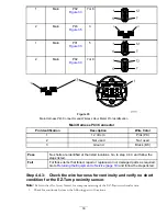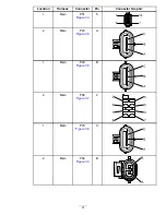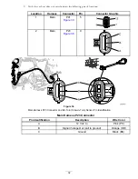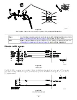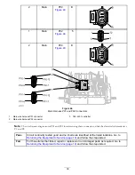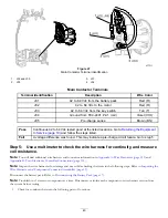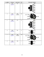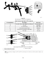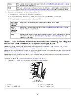
Fault 03 5 V Supply
InfoCenter Display:
5 V Supply Fault
Fault Description
The 5 Vdc regulator on the TEC-2401 is not able to maintain regulation at an acceptable voltage level.
Circuit Description
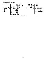
The TEC-2401 has an internal DC-DC converter that supplies 5 Vdc power for various circuits including the speed-control
position sensor potentiometer.
Conditions for Setting the Fault
The TEC-2401 checks and then monitors for proper voltage. If the 5 Vdc output is not maintaining regulation (dropping
below 4.91 Vdc), the system will trigger the fault.
Note:
The most likely cause for this fault is a short circuit of the 5 Vdc supply line.
Recommended Service Actions
Step 1:
Verify that the fault repeats.
1.
Clear the InfoCenter fault log. Refer to
Clearing the InfoCenter Fault Log (page 19)
.
2.
Disconnect the battery pack for 30 seconds. Refer to
Disconnecting the Battery Pack (page 17)
.
3.
Connect the battery pack. Refer to
Connecting the Battery Pack (page 17)
.
4.
Start and operate the machine. Refer to the
eFlex Operator’s Manual
.
Pass
The fault did not repeat. Go to
Returning the Equipment to Service (page 19)
and follow the
steps listed.
Note:
If the fault does not repeat, a false detect event may have occurred.
Fail
The fault repeated. Go to step 2.
Step 2:
Check the charge level of the battery.
Check the InfoCenter LCD screen to ensure that the charge level is adequate. If the battery indicator does not show at least 1
full block, connect the battery charger to the battery pack and charge the battery pack to at least 40% capacity.
Step 3:
Remove 2 access covers to aid troubleshooting.
Performing these steps provides access to connectors on the wire harnesses.
1.
Remove the console cover. Refer to
Console Cover (page 19)
.
2.
Remove the power center cover. Refer to
Power Center Cover (page 20)
.
Step 4:
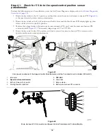
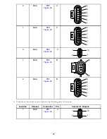
Use a multimeter to perform voltage and continuity checks for the speed
control position-sensor potentiometer.
Note:
You will find additional wire harness and connector information in
Appendix A: Wire Harnesses (page 113)
and
Appendix B: Toro Electronic Controller Connections (page 135)
.
Note:
Refer to the testing instructions for the speed-control potentiometer component in the
eFlex Service Manual
Chapter 4,
Electrical System, Component Testing section.
35

